
Multivibrator

The BJT collector-cross-coupled monostable multivibrator circuit operates as follows: Upon powering up, the base of transistor T2 is connected to the supplied voltage through the biasing resistor R2, causing T2 to be "ON" and conduct. This connects the base of T1 to ground through resistor R3, turning T1 "OFF" and establishing the stable state with zero output. When a momentary switch (SW) is pressed, a short circuit is created between the collector of T1 and ground, causing capacitor C to discharge quickly. This results in the base voltage of T2 dropping below zero volts, turning T2 "OFF." With T2 "OFF," the base of T1 is connected to the supplied voltage through R4 and R3, turning T1 "ON." The circuit remains in this unstable state for a duration determined by the values of capacitor C and resistor R2. As capacitor C charges, the base voltage of T2 increases and turns "ON" once it exceeds 0.7V.
The term "bi" means two, indicating that a bistable multivibrator has two stable states. Upon receiving an external triggering signal or pulse, the circuit switches from its current stable state to the other and remains in this state until another external signal is received. This circuit can function as an alternating on/off circuit. The BJT collector-cross-coupled bistable multivibrator circuit operates as follows: At power-up, assuming T1 is "ON," its collector is at ground voltage, resulting in T2 being "OFF," which connects the base of T1 to the supplied voltage via R4 and R3. This state is known as the set state, with a high output. The circuit remains in this state until the reset switch is pressed, which connects the base of T1 to ground, forcing it to turn "OFF." Consequently, the base of T2 is connected to the supplied voltage via R1 and R2, turning T2 "ON." The circuit remains in this state until the set switch is pressed.
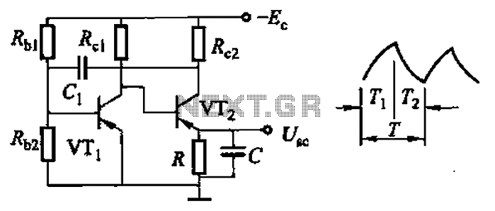
An astable multivibrator does not have a stable state; it continually alternates between states without any external signal, functioning as an oscillator that produces a repetitive output signal. Astable multivibrators are essential in power inverters and are used to generate buzzing sounds of varying tones when connected to a speaker. They are also commonly employed in light flashers. The most prevalent type of astable multivibrator is the cross-coupled transistor switching circuit, which consists of two switching transistors and a cross-coupled feedback network of timer components that facilitate oscillation between the two states without requiring an external triggering signal. The timer components consist of resistors and capacitors, and the period of a complete cycle can be calculated using a specific equation. Although both sides of the circuit are identical, one transistor will conduct before the other due to an inherent imbalance in the circuit.Multivibrators are two-state (high or low) output circuits. These include oscillators, timers and flip-flops. Multivibrators are mostly used in applications which involve timing, pulse generation or pulse triggering of other device and so on. There are three types of multivibrators, these are monostable, bistable and astable. `mono` means one or s ingle, therefore monostable multivibrator is a single-stable state multivibrator with other state unstable or transient. A triggering signal/pulse is needed for this circuit to change to its unstable state which last for a fixed period preset by timer components of the circuit before returning to its stable state.
This circuit finds application in a system where a timing period of fixed duration is needed in response to external event. Above is a BJT collector-cross-coupled monostable multivibrator circuit. At the instance of power up, the base of transistor T2 is connected to supplied voltage via the biasing resistor, R2 hence T2 is `ON` and it conducts.
T2 connects the base of T1 to the ground via resistor, R3, turning T1 `OFF`. This is the `Stable State` with zero output. If momentary switch, SW is pressed, a short circuit is applied between the collector of T1 and the ground forcing capacitor, C to discharge quickly with base voltage of T2 drop below zero volt, T2 goes `OFF`. With T2 `OFF`, base of T1 is connected to the supplied voltage via R4 and R3, hence T1 is `ON`. The circuit remains in this state for a period determined by the value of capacitor, C and resistor, R2.
This is the `Unstable State`. As C begins to charge up, base voltage of T2 increases and turns `ON` immediately it is above 0. 7V. The duration of the pulse is given by the formula. `bi` means two, therefore bistable multivibrator is a two-stable state multivibrator. That is, on receiving of an external signal (triggering signal/pulse), the circuit changes its present stable state to other and remains in this state until next external signal is received. This circuit can be used as an alternate on/off circuit. In fact in my article ` alternate on/off circuit `, alternate on/off circuit is called bistable multivibrator and that is it.
Above is a BJT collector-cross-coupled bistable multivibrator circuit This circuit choose either of the states at the instance of power up. Assuming T1 is on at the instance of power up, its collector is at ground voltage, hence base of T2. As a result of this, T2 is `OFF` connecting base of T1 to the supplied voltage via R4 and R3. This state is the set state as the output is high. The circuit will remain in this state unless reset switch is pressed. Pressing the reset switch connects the base of T1 to the ground forcing it to go `OFF`. At this stage, base of T2 is connected to the supplied voltage via R1 and R2 which turns T2 `ON`. Also the circuit remains in this state until the set switch is pressed. This multivibrator has no stable state -it continually flips from one state to the other without any external signal being applied.
It is an oscillator in the sense that it produces a repetitive output signal. Astable multivibrator is an important circuit in any power inverter, it also finds great use or application in generating buzzing sound of different tones by varying the frequency when connected to a speaker. Another good application of an astable multivibrator is in light flasher. The most common type of astable multivibrator is the cross-coupled transistor switching circuit. This circuit consists of two witching transistors and cross-coupled feedback network of a pair of timer components which allow oscillation between the two states with no external triggering signal.
The timer components are the resistor and the capacitor. The period of a complete cycle is given by the equation below. Though the two sides of the circuit are identical, one of the transistors will conduct before the other due some imbalance in t 🔗 External reference
Related Circuits
A multivibrator is a relaxation oscillator that utilizes two tubes, transistors, or other electronic devices. A multivibrator circuit is a type of oscillator that generates a square wave output. It typically consists of two active devices, such as transistors or...
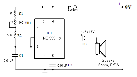
Function: to trigger a device or operate in free-running mode. Components: Battery, Charger, Battery Connector, Capacitor, Integrated Circuit (IC), Resistor VR1-10K, Resistor R1-1K, Resistor R2. The described circuit functions either to trigger a connected device or to operate in a...
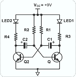
This circuit is basically simple and easy to build, it uses two transistors as active components and a few passive components like resistors, capacitors and two LEDs. The circuit makes use of the MPS2222 transistor. You can use any...
This circuit is straightforward and easy to construct, utilizing two transistors as active components along with several passive components such as resistors, capacitors, and two LEDs. The circuit employs the MPS2222 transistor, though any NPN type transistor can be...
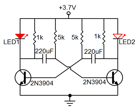
Many friends have requested an automatic on/off LED circuit or an LED flashing circuit. This post presents an astable multivibrator circuit designed for LED flashing. It is a simple astable multivibrator circuit utilizing two LEDs (specifically red LEDs) and...
Common non-sinusoidal oscillator circuit, waveform and frequency formula - sawtooth oscillator - use multivibrator. The sawtooth oscillator is a type of non-sinusoidal waveform generator that produces a triangular or sawtooth-shaped output signal. This oscillator is commonly utilized in various applications,...