
8W Fluorescent Lamp Inverter circuit

The 8W inverter circuit employs a ZTX652 transistor as the primary switching element, which is critical for converting the low-voltage DC input into a higher-voltage AC output suitable for fluorescent lamps. The design accommodates input voltages from 10V to 16.5V, making it versatile for various 12V power sources, including automotive batteries. The efficiency of up to 78% indicates a relatively low power loss, making it suitable for applications where battery life is a concern.
The separate oscillator design is a notable feature, allowing for frequency adjustments that can optimize performance based on the load characteristics. This flexibility is advantageous when powering devices with different operational requirements. The inverter's capability to drive devices such as electric razors and stroboscopes highlights its practical applications in both household and professional settings.
In contrast, the 1000W inverter circuit based on the RFP50N06 MOSFETs is designed for more demanding applications. The circuit can handle significant loads, making it suitable for larger devices or multiple smaller devices connected in parallel. The use of heatsinks is essential in this design to manage the thermal performance of the MOSFETs, ensuring reliability and longevity during operation.
The inclusion of a square wave generator and amplifier stage in the inverter diagram is crucial for producing the necessary AC waveform. The configuration of transistors Q1 and Q2 as the square wave generator ensures that the output waveform is suitable for driving transformers effectively, while transistors Q5 to Q8 serve to amplify the generated signal, enhancing the output current to meet the demands of the connected load. The transformer plays a vital role in stepping up the voltage from the low DC levels to the required AC levels, making this inverter circuit a practical solution for applications needing AC power from a DC source.This circuit is basically a 8W inverter circuit. The circuit continues to be intended to drive an 8W fluorescent lamp from a 12V power supply, utilizing an cheap inverter primarily based on a ZTX652 transistor. The inverter will operate from supplies in the variety of 10V to 16. 5V, obtaining efficiencies up to 78% as a. This inverter circuit can be used to power electric razors, stroboscopes and flash tubes, and small fluorescent lamps from a 12 volt car battery. In contrast to the usual feedback oscillator type of inverter, the oscillator of this inverter is separate from the output stage, which allows easy adjustment of the oscillator frequency to suit.
Here`s a very simple circuit inverter that converts DC current into AC current, from 12V DC to 220V AC with output power of 5W. Inverter circuit is typically used for emergency lighting, since the power output is small, which is about 5W only.
But you can use this inverter for other purposes that do not. 1000W Power Inverter circuit diagram: This is the power inverter circuit based MOSFET RFP50N06. The inverter capable to handle loads up to 1000W, it`s depended on your power inverter transformer. The RFP50N06 Fets are rated at 50 Amps and 60 Volts. Heatsink is required for cooling the MOSFETs. You may add some MOSFETs with parallel. The following diagram is an inverter circuit which will give you 220V AC 50Hz with maximum power of 100W. This inverter built using transistors both the square wave generator and the amplifier. Inverter Diagram: The Q1 and Q2 used generate square wave. Q5-Q8 amplify the signal and the transformer to increase the AC/square wave current. 🔗 External reference
Related Circuits
The sunset lamp activates at full brightness and gradually dims over a duration of 1.5 hours, remaining off until the power is reset. The sunset lamp circuit is designed to simulate the natural fading of sunlight, providing a calming effect...

The BFP640 transistor is utilized for 1575 MHz Global Positioning Satellite (GPS) applications, specifically as a Low Noise Amplifier (LNA). The design objectives include a minimum gain of 16 dB, a noise figure of less than 0.6 dB, an...

The TEA5551T monolithic integrated radio circuit can be utilized to design an AM radio receiver, intended for use as a portable radio receiver with headphones. The TEA5551T radio receiver circuit encompasses all necessary components for a complete AM receiver,...
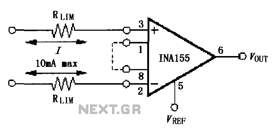
The input current protection circuit is illustrated in FIG, utilizing INA155/156. The INA155 features internal electrostatic discharge (ESD) protection diodes that become active when the input voltage exceeds the supply voltage by 500mV. In this scenario, the protection diodes...
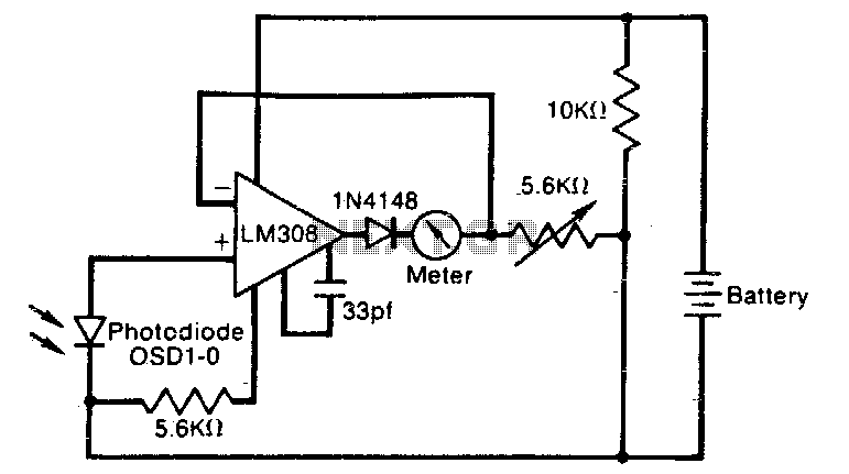
The meter reading is directly proportional to the logarithm of the input light power. The logarithmic circuit behavior arises from the nonlinear diode p-n junction current/voltage relationship. The diode in the amplifier output prevents the output voltage from becoming...
A varying brightness AC lamp circuit utilizes a silicon-controlled rectifier (SCR) to gradually adjust the intensity of a 120-volt light bulb by controlling the duration of AC line voltage applied to the lamp during each half cycle. The circuit...