
12V Vehicle Electrical Wiring Tester Circuit

The 12V vehicle electrical wiring tester circuit is designed to provide a simple yet effective means of verifying the integrity of electrical circuits within automotive applications. The primary components of this circuit include two light-emitting diodes (LEDs), a resistor, and the necessary connections for interfacing with the vehicle's electrical system.
The circuit operates on a 12V power supply, which is standard for most vehicles. When the tester is connected to a live circuit, one of the LEDs will illuminate, indicating that the circuit is active. Conversely, if the circuit is not live, the second LED will light up, providing a clear visual indication of the circuit's status. This dual LED configuration allows for quick and easy diagnostics, enabling technicians and DIY enthusiasts to ascertain the operational state of various electrical components, such as lights, ignition systems, and other accessories.
To construct this circuit, a resistor is typically included to limit the current flowing through the LEDs, thereby preventing damage and ensuring longevity. The circuit can be housed in a durable enclosure to protect it from environmental factors typically encountered in automotive settings.
Connections to the vehicle's electrical system can be made using alligator clips or other suitable connectors, allowing for easy attachment and detachment. This tester is particularly valuable for troubleshooting issues related to wiring faults, blown fuses, or malfunctioning components, making it an essential tool for anyone working with vehicle electronics.12V Vehicle Electrical Wiring Tester Circuit This little tester is useful for checking vehicle electrical circuits. Two LEDs indicate whether.. 🔗 External reference
Related Circuits

Samsung C3330 Circuit Diagram Download Manual PDF Download. The Samsung C3330 circuit diagram serves as a comprehensive reference for understanding the electronic architecture of the device. This schematic provides detailed insights into the interconnections between various components, including the microcontroller,...

The diagram is useful when replacing components as it shows component locations. It also identifies the wires by specific colors and indicates the terminals of components to which the wires are connected. The most common types of diagrams are...

The DC voltage present on the telephone line typically ranges from 45 to 50V when on-hook and drops to approximately 6V when off-hook. This condition activates a step-down circuit relay, which in turn controls a tape recorder. Audio input...
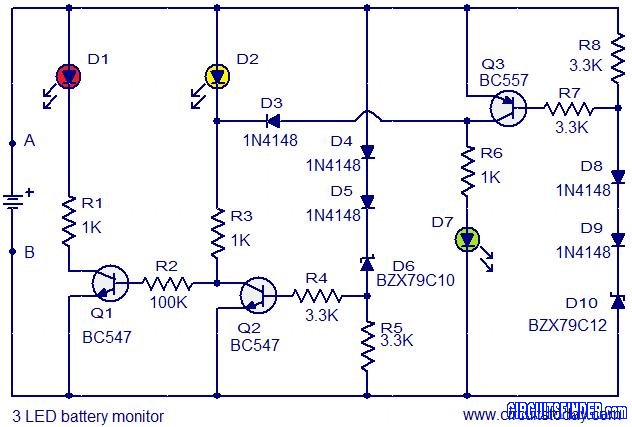
This is the circuit diagram of a 3 LED bar graph type battery monitor circuit that is ideal for monitoring the voltage level of an automobile battery. When battery voltage is 11.5V or less, transistor Q1 will be on...
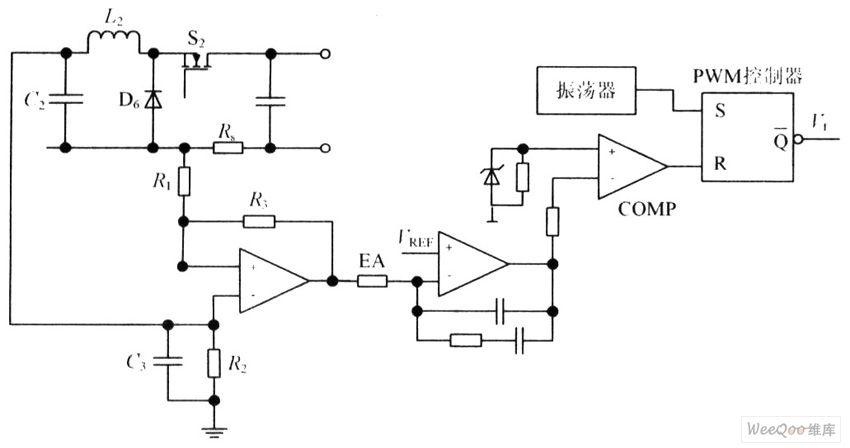
The circuit is capable of enhancing the system power factor to a value exceeding 0.99. It effectively reduces the waveform distortion of the input supply current, ensuring compliance with GB15144 standards, with a distortion index lower than level L....

The schematic diagram of the MS Decoder may appear complex, but it is relatively straightforward. Initially, both the Mid and Side signals are buffered using unity gain inverting buffers, which are constructed around IC1b and IC2b. This buffering serves...