
Protection Circuit For Electrical Appliances From Power Supply Variations PCB
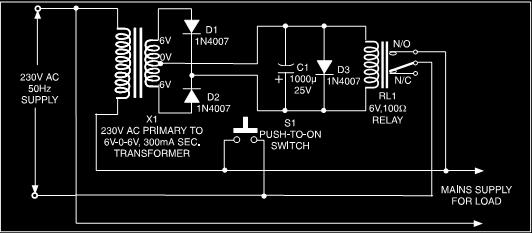
The circuit design incorporates a step-down transformer (X1) that reduces the mains voltage to a safer level suitable for the components in the circuit. The full-wave rectifier converts the alternating current (AC) output from the transformer into direct current (DC), which is essential for powering the relay and the control logic. The capacitor C1 plays a crucial role in smoothing the rectified output, ensuring a steady DC voltage is available to energize relay RL1.
Relay RL1 is a key component in this circuit, acting as an automatic switch that disconnects the load from the mains supply during a power outage. In its de-energized state, the relay opens the circuit, effectively isolating the load from the mains. When the circuit is initially powered, the user can manually close switch S1, energizing the relay and allowing current to flow through the transformer and load. This momentary action is critical since it enables the relay to maintain its energized state, creating a continuous path for the power supply until an interruption occurs.
Upon detecting a power interruption, the relay will automatically de-energize, cutting off the load from the mains supply. This feature protects sensitive appliances from potential damage caused by sudden voltage fluctuations. Once the mains power resumes, the user must press switch S1 again to re-establish the connection, ensuring that the appliances are not inadvertently reconnected during unstable conditions.
Overall, this low-cost protection circuit is an effective solution for safeguarding home appliances from the risks associated with erratic power supply conditions, providing both safety and manual control over the restoration of power.Here is a very low-cost protection circuit to save your electrically operated home appliances, such as TV, DVD player, refrigerator, and other instruments during sudden tripping and resumption of mains supply. Appliances like refrigerators and air conditioners are more sensitive to damages due to such mains supply variations.
Thus the circuit prov ides suitable safety against erratic power supply conditions. The simple circuit given here switches off the mains supply to the load as soon as the power trips. The supply can be resumed only by manual intervention. Whenever the supply is found to be stabilized, then it switch on. The circuit consist of a step down transformer followed by a full wave rectifier. The capacitor C1 act as a filter or smoothing capacitor which act as a power supply source for relay RL1. Initially, when the circuit is switched on, the power supply path to the step-down transformer X1 as well as the load is incomplete, as the relay is in de-energised state.
The relay can be energised by the switch S1 for a short period of time. This completes the path for the supply to transformer X1 as also the load via closed contacts of switch S1. Meanwhile, the supply to relay becomes available and it gets energised to provide a parallel path for the supply to the transformer as well as the load.
If there is any interruption in the power supply, the relay activates Thus, once the supply is interrupted even for a short period, the relay is de-energized and you have to press switch S1 momentarily (when the supply resumes) to make supply available to the load. 🔗 External reference
Related Circuits
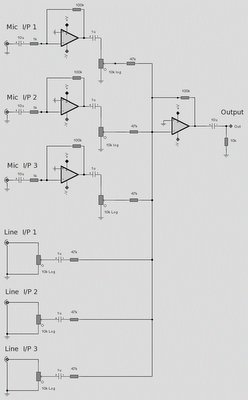
The microphone inputs are amplified approximately 100 times or 40 dB, with the total gain of the mixer, including the summing amplifier, reaching 46 dB. The microphone input is designed for microphones that produce an output of around 2...

This circuit utilizes a voltage-controlled oscillator (VFO) operating in the frequency range of 15 to 18 MHz (U1), which feeds into a balanced mixer (U2). A fixed oscillator signal is combined with the VFO output to produce an output...
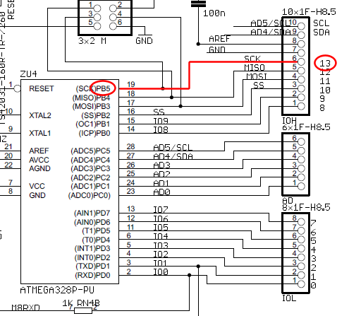
The wire connected to the 5V pin is linked to the positive pins of the breadboard, which are not connected to any other components. There are no additional connections on the positive column. While this may seem like a...
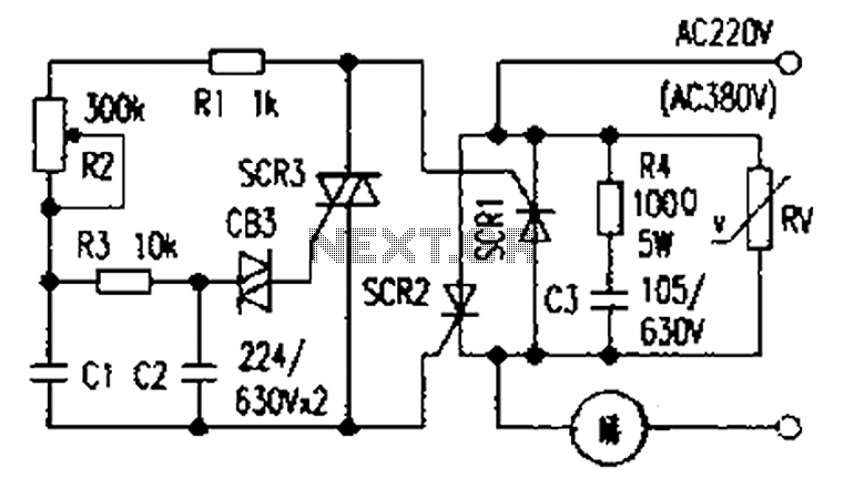
The presentation of a general power thyristor trigger circuit is more complex, and some components are difficult to procure. A successful trigger circuit has been constructed for only a few dollars. This circuit is designed to trigger a thyristor...
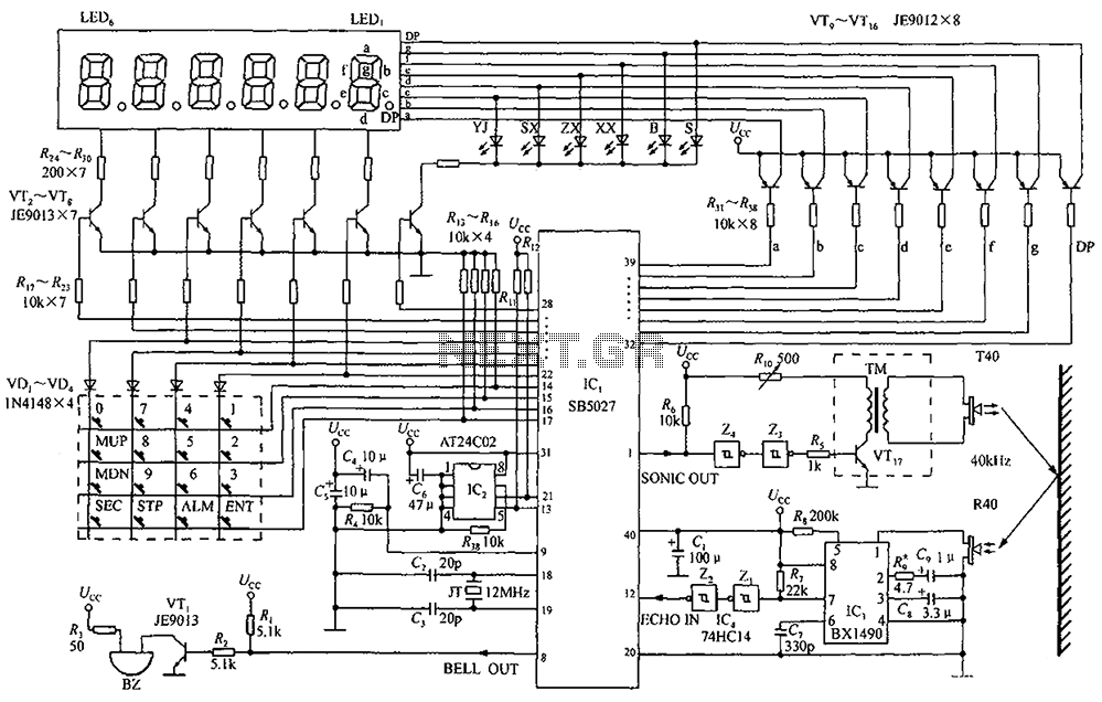
A circuit diagram of an ultrasonic range finder is constructed using a clock with a calendar and the Ultrasonic Ranging IC SB5027. The ultrasonic range finder circuit utilizes the Ultrasonic Ranging IC SB5027, which is designed to measure distances by...
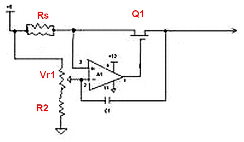
Assuming a 5V output can be achieved after adjusting the potentiometer, will the 240-ohm resistor limit the current, or is there a need to add additional components? If it does limit the current, it is expected that the power...