
22 Watt Car Subwoofer Amplifier

The described circuit serves as an effective solution for enhancing the audio experience in automotive environments by integrating a dedicated subwoofer. The use of the BTL amplifier configuration allows for efficient power delivery while minimizing component count, making the design both economical and practical for automotive applications. The phase control feature enables fine-tuning of the acoustic alignment between the subwoofer and the main speakers, ensuring a cohesive soundstage.
The low-pass filter's adjustable cutoff frequency is critical for tailoring the audio output to suit personal preferences or specific vehicle acoustics. By allowing the user to select a frequency range between 70Hz and 150Hz, the circuit accommodates various musical genres and listening environments, optimizing bass response without overwhelming other audio frequencies.
The inclusion of a DC voltage stabilizer is a vital design consideration, ensuring that the sensitive input and filtering stages maintain stable operation despite fluctuations in the power supply. This stability is particularly important in automotive settings, where electrical noise and voltage variations can occur. The time delay before the amplifier reaches full operational status is a common design feature that prevents potential damage to the circuitry during power-up and ensures that the system is ready for use without abrupt transitions.
Overall, this design provides a robust and flexible solution for integrating a subwoofer into existing car audio systems, enhancing the listening experience while maintaining a user-friendly interface.This unit is intended to be connected to an existing car stereo amplifier, adding the often required extra "punch" to the music by driving a subwoofer. As very low frequencies are omnidirectional, a single amplifier is necessary to drive this dedicated loudspeaker.
The power amplifier used is a good and cheap BTL (Bridge Tied Load) 13 pin IC made by Philips (now NXP Semiconductors) requiring a very low parts count and capable of delivering about 22W into a 4 Ohm load at the standard car battery voltage of 14. 4V. The stereo signals coming from the line outputs of the car radio amplifier are mixed at the input and, after the Level Control, the signal enters the buffer IC1A and can be phase reversed by means of SW1.
This control can be useful to allow the subwoofer to be in phase with the loudspeakers of the existing car radio. Then, a 12dB/octave variable frequency Low Pass filter built around IC1B, Q1 and related components follows, allowing to adjust precisely the low pass frequency from 70 to 150Hz.
Q2, R17 and C9 form a simple dc voltage stabilizer for the input and filter circuitry, useful to avoid positive rail interaction from the power amplifier to low level sections. Due to the long time constant set by R17 and C9 in the dc voltage stabilizer, the whole amplifier will become fully operative about 15 - 30 sec.
after switch-on. 🔗 External reference
Related Circuits
The circuit is drawn for measurement of acceleration from 1000 mg until + 1000 mg. It can be placed in the car and be supplied from the sheath of the electric lighter. The circuit includes one indicative LED and...
This circuit is similar to the previous one but utilizes positive feedback to increase the amplitude to the speaker. It was adapted from a small 5-transistor radio that employs a 25-ohm speaker. In the prior circuit, the load resistor...
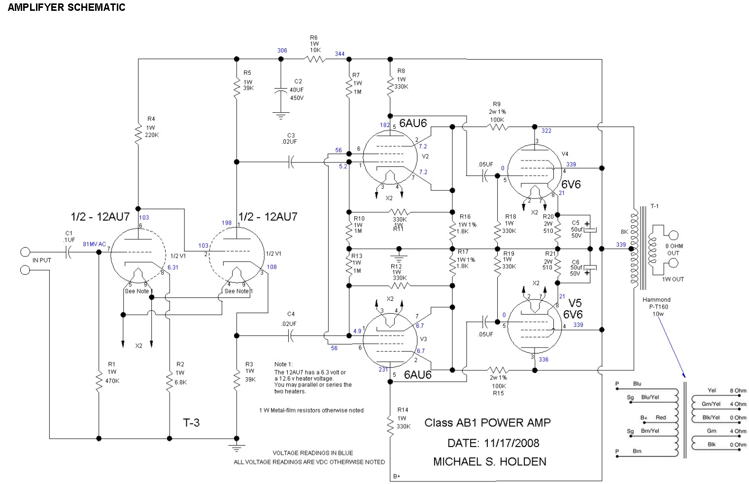
Inquiry regarding the suitability of a design for a first tube amplifier build, along with a request for recommendations on suitable components. The inquiry pertains to the construction of a tube amplifier, which is a type of audio amplifier that...
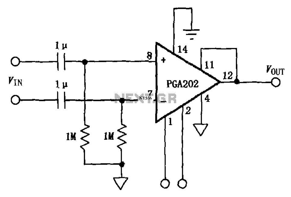
The circuit illustrated in FIG PGA202 comprises an AC-coupled differential amplifier. The input stage of PGA202 includes two 1 µF capacitors and two 1 MΩ resistors, resulting in a cutoff frequency of approximately 0.16 Hz. The Qualcomm AC coupling...
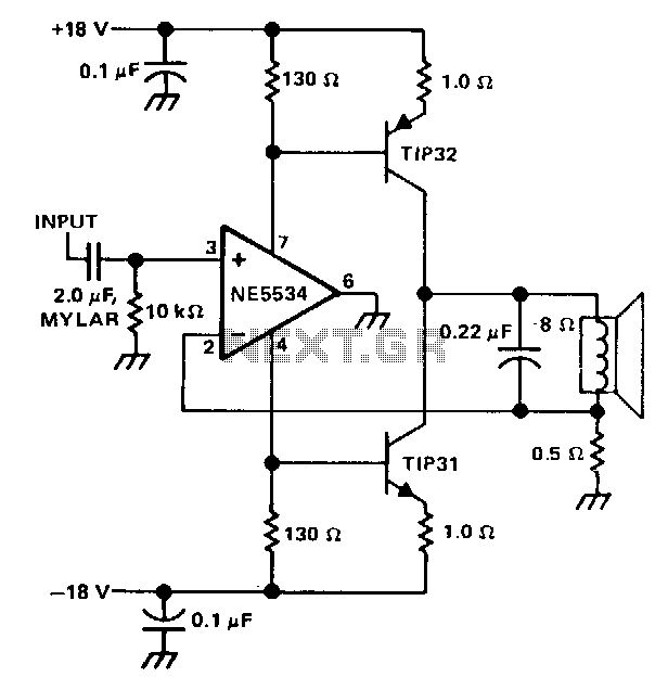
The single speaker amplifier circuit utilizes current feedback instead of the more commonly used voltage feedback. The feedback loop originates from the junction of the speaker terminal and a 0.5-ohm resistor, connecting to the inverting input of the NE5534...
The following schematic illustrates a 5.8W stereo power amplifier utilizing the Samsung IC KA2211. Each channel delivers a power output of 5.8W, resulting in a maximum combined output of 2 x 5.8W. The KA2211 is a dual audio power...