
220 Volts Flashing Lamps

This circuit functions as a flashing controller for Christmas tree lights, effectively replacing traditional thermal switches with a solid-state solution. The primary components include two transistors (Q1 and Q2) that act as a trigger mechanism for the Silicon Controlled Rectifier (SCR). The resistors R1 and R2, along with the capacitor C1, create a timing circuit that dictates the flash rate of the lights.
To fine-tune the flashing frequency, the capacitance of C1 should be adjusted rather than the resistors R1 and R2. This design choice allows for a wider range of flashing frequencies by simply changing the capacitor's value within the specified limits. The recommended values of C1 (470 or 1000 µF) and R4 (12K or 10K) have been determined through testing to provide the best performance in this application.
The circuit is designed to operate with minimal power, making it suitable for the low current requirements of typical Christmas tree light setups, which draw about 60mA at 220V. This low power consumption enables the use of compact and economical SCRs, such as the C106D1 or TICP106D, both of which are capable of handling the circuit's demands without overheating or failing.
In instances where these SCRs are not available, the circuit can be adapted to utilize Triacs, which are also effective for this application. The TIC206M Triac is a commonly used component that can replace the SCR while maintaining the circuit's functionality. The inclusion of the diode bridge (D1-D4) is critical to the circuit's operation, ensuring that the current is appropriately managed regardless of whether an SCR or Triac is used. This diode bridge allows for the necessary rectification and protection of the circuit components, contributing to the overall reliability and performance of the flashing controller.This circuit is intended as a reliable replacement to thermally-activated switches used for Christmas tree lamp-flashing. The device formed by Q1, Q2 and related resistors triggers the SCR. Timing is provided by R1, R2 & C1. To change flashing frequency don`t modify R1 and R2 values: set C1 value from 100 to 2200 µF instead.
Best performances are o btained with C1=470 or 1000 µF and R4=12K or 10K. Due to low consumption of normal 10 or 20 lamp series-loops intended for Christmas trees (60mA @ 220V typical for a 20 lamp series-loop), very small and cheap SCR devices can be used, e. g. C106D1 (400V 3. 2A) or TICP106D (400V 2A), this last and the suggested P0102D devices having TO92 case. If you are unable to find these devices you can use Triacs instead. In this case the circuit operates also with relatively powerful devices. A recommended Triac type is the ubiquitous TIC206M (600V 4A) but many others can work. Note that in spite of the Triac, diode bridge D1-D4 is in any case necessary. 🔗 External reference
Related Circuits
This circuit is similar to the LED clock using 12 neon indicator lamps instead of LEDs. It operates from 2 high capacity ni-cad cells (2.5 volts) which keep it going for a couple weeks. High voltage (70 volts) for...
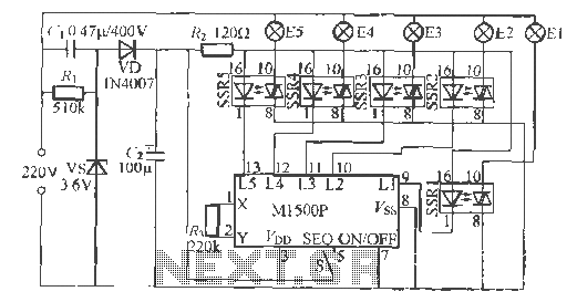
The Shenzhen Skywave Semiconductor Co., Ltd. produces a five-flash integrated circuit controller known as M1500P. This device is manufactured using a DIP 14 standard package and can be customized according to customer specifications for soft seal packaging. It operates...
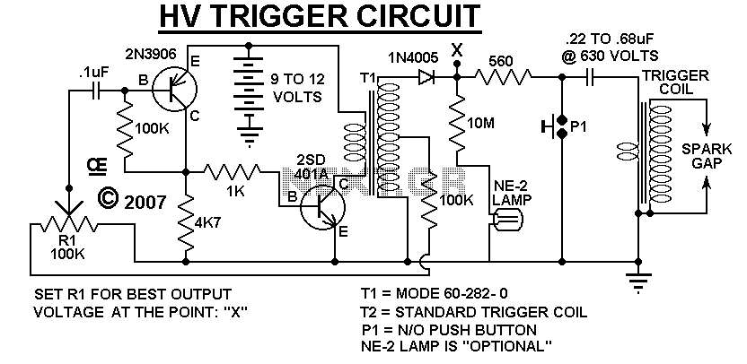
A Very Low Current, High Voltage Spark, that is Manually Triggered. Although its not easily Measured, the Peak Output voltage will be over 5,000 Volts. T1 is a small audio transformer and it steps up the voltage to about...
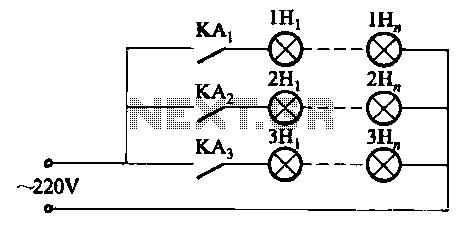
The relay control system utilizes multiple pairs of contacts, allowing for the connection of higher power lamps in parallel. The circuit design is straightforward; by altering the capacitance of the capacitor, different flashing frequencies can be achieved. The described circuit...
The objective is to transmit additional information through the distribution of articles. Please contact us via email at [email protected] within 15 days if there are any issues related to article content, copyright, or other concerns. Prompt action will be...

A simple touch dimmer circuit diagram using the TT6061 IC, which is a touch control integrated circuit used for light dimmer circuits and lamp dimmer circuits. The touch dimmer circuit utilizing the TT6061 IC is designed to provide a user-friendly...