
Low-noise differential amplifier circuit composed PGA203 and OPA27

The circuit design incorporates the PGA203 as a key element in achieving a high-input impedance and low-noise performance. The PGA203 is particularly suited for applications requiring precision signal amplification, as it minimizes the impact of common-mode signals that can introduce noise and distortion. The two OPA27 op amps are utilized in a non-inverting configuration, which further enhances the signal integrity while providing the necessary gain.
The overall gain of the circuit is determined by the product of the gains from the PGA203 and the two OPA27 op amps. This modular gain structure allows for flexibility in application, enabling the circuit to be tailored to specific signal amplification requirements. The combination of the PGA203 and OPA27 op amps not only ensures high performance but also maintains stability across a range of input conditions.
In practical applications, this differential amplifier configuration is ideal for sensor interfacing, data acquisition systems, and other scenarios where low-noise amplification of differential signals is critical. The careful selection of components and their arrangement in the circuit contributes to the overall reliability and effectiveness of the amplifier in processing weak signals while rejecting unwanted noise. As shown in FIG grounds PGA203 op amp OPA27 constitute a low noise differential amplifier. The circuit at the input PGA203 plus two op amps OPA27, signals from the two op amps noninverting input terminal, using two op amps noninverting amplifier PGA203 high impedance differential input characteristics, the common mode noise rejection to Min. Gain two op amps OPA27 composed of 100, PGA203 gain 1,2,4,8, multiplying the two, so the total gain of the circuit 100,200,400,800.
Related Circuits
This article explains how to construct a general-purpose DTMF decoder using an affordable chip from MITEL. The circuit supports DTMF squelch based on a three-digit station ID (covering all 999 combinations). It can also decode four additional commands, which...
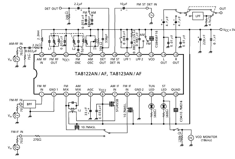
A simple low-power AM/FM radio receiver electronic project can be designed using the TA8122 integrated AM/FM receiver, manufactured by Toshiba Semiconductor. This radio receiver circuit can be utilized for portable radio applications or similar devices. The TA8122 radio receiver...
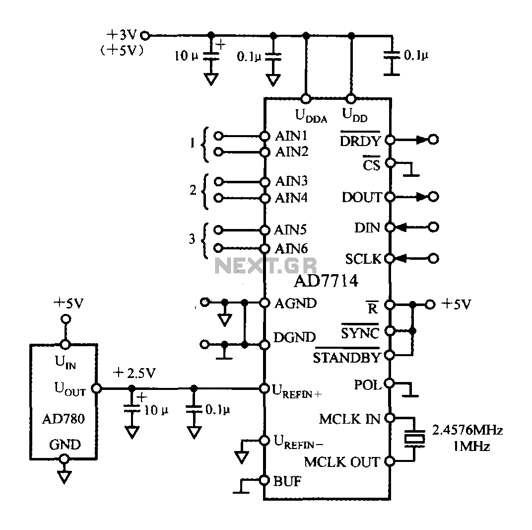
The typical application circuit for the AD7714 is illustrated in the accompanying figure. The UDD and UDDA terminals of the AD7714 can be connected to either a +3V or +5V power supply. The analog inputs are arranged as three...
Circuit diagram for a mini emergency lamp. This mini emergency lamp activates during power failures to provide cool white light in the room. It utilizes a 1-watt white LED to deliver adequate illumination. The circuit for the mini emergency lamp...
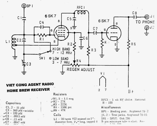
Army Radio Sales Co. specializes in military communications equipment for ham radio operators and collectors. The company offers a variety of military radios from various countries for sale and also engages in the buying and swapping of military radios...
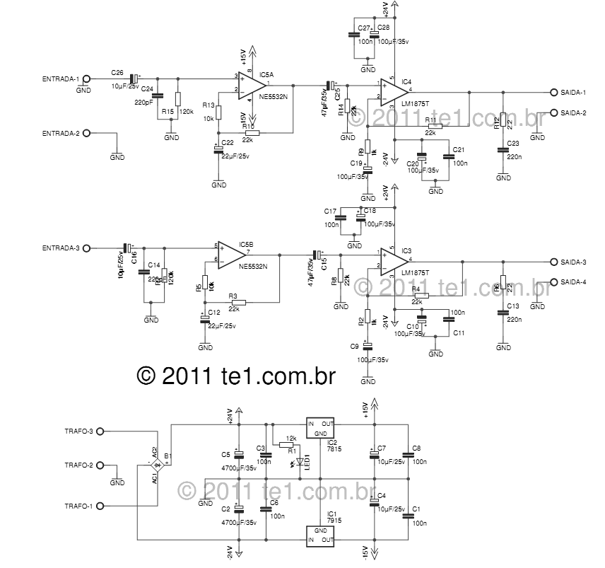
The LM1875 delivers 20 watts into a 4 or 8-ohm load on ±25V supplies. Using an 8-ohm load and ±30V supplies, over 30 watts of power may be delivered. The amplifier is designed to operate with a minimum of...