
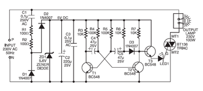
220V 200W Bulb flasher

This circuit is designed as a simple power flasher, suitable for applications where a flashing light is required without the need for complex circuitry. The primary component of this circuit is a Silicon Controlled Rectifier (SCR), which serves as a switch to control the power delivered to the load—typically a 100W incandescent bulb. The circuit operates at a frequency of approximately 1Hz, creating a flashing effect with a 50% duty cycle, meaning the light is on for half the duration of each cycle.
The maximum load capacity of this circuit is 200W, allowing for the use of higher wattage bulbs if necessary. However, it is essential to note that the frequency of the flashing can be adjusted by changing the capacitance value of the capacitor in the circuit. Increasing the capacitance will lower the frequency, while decreasing it will raise the frequency, thus providing flexibility in the design.
While the circuit has not been tested at 110VAC, it is anticipated that it would function correctly with appropriate adjustments to the resistor values—specifically, reducing them to about half of their stated values to accommodate the lower voltage. The SCR used in this design is from Siemens but can be replaced with any equivalent semiconductor that has standard gate sensitivity characteristics.
Safety precautions are critical when working with circuits connected directly to the mains. It is imperative to ensure that all components are rated for the voltage and current they will encounter in operation. A more modern iteration of this circuit might incorporate a sensitive gate SCR for improved performance, along with low power resistors and a 10µF, 250V electrolytic capacitor, which would enhance reliability and efficiency while maintaining the desired functionality. Proper isolation and protective measures should always be employed to mitigate risks associated with high voltage operation.There is no need to resort to complex circuitry if what you are looking for is a simple power flasher. The light will flash at around 1Hz with a 100W bulb at a duty cycle of 50%. The max. load that can be driven with this circuit is 200W and if you wish to have a different frequency you have to change the value of the capacitor.
Operation at 110VAC has not been tested although I expect it to work provided the resistors are set at about half the stated value. The SCR is manufactured by Siemens but any other equivalent semiconductor, with standard gate sensitivity, should work fine.
WARNING! - This circuit is directly connected to the mains and proper safety precautions should be taken. A more modern design would use a sensitive gate SCR, other low power resistors and a 10?F, 250V electrolytic capacitor. 🔗 External reference
Related Circuits
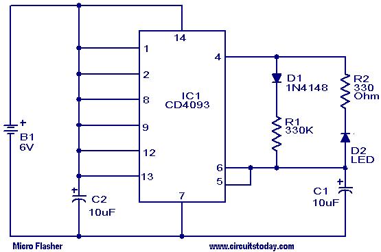
This micro flasher circuit continuously emits a flashing light while consuming very little power. The circuit can operate for an extended period using four 1.5V torch cells. A low-power CMOS IC, the CD4093 (IC1), is utilized to generate sharp...
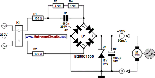
This circuit concept is not new, but it is useful when deciding between a small, short-circuit-proof transformer or a capacitive voltage divider for powering a fan directly from 230 V mains voltage. In situations where forced cooling is an...
The schematic circuit design is for a 250-watt output inverter. To increase the power of the circuit, additional Q7 and Q8 transistors can be added in parallel; each pair contributes an additional 250 watts. For instance, to achieve 750...
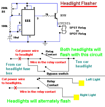
This circuit enables car headlights to flash on and off simultaneously or alternately. It is based on the 555 timer operating in astable mode. The output of the 555 timer will go high for an adjustable period and then...
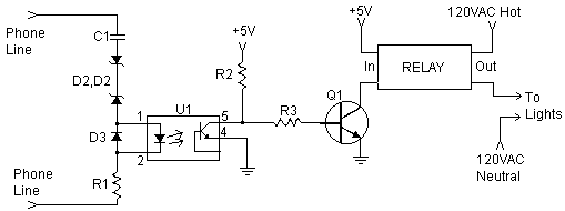
This document explains how to connect lights so that they flash when the phone rings. This setup is particularly beneficial in noisy environments, such as workshops, where it is challenging to hear the phone ringing. The ring detection component...
Components such as resistors R1 and R2, capacitors C1, C2, and C3, diodes D1 and D2, and a zener diode ZD1 are utilized to create a stable 5V DC supply voltage that delivers the necessary current to operate the...