
Simple audio mixer circuit with fet 2n3819

This simple mixer circuit is designed to efficiently combine two audio signal channels into a single output, making it ideal for applications where space and power consumption are critical. The use of a codec circuit is instrumental in converting stereo audio to mono, ensuring compatibility with various audio systems that may only support mono inputs.
The addition of variable resistors VR1 and VR2 allows for fine-tuning of the audio levels from each input channel, providing flexibility in mixing. Resistors R1 and capacitor C1 can be adjusted to modify the circuit's response to different audio sources, enabling customization based on user requirements or specific application needs.
The low current consumption characteristic of this circuit makes it particularly advantageous for portable applications, as it can operate effectively on a 9-volt battery, extending the operational life of the device.
The audio signal path begins with the incoming voice signals at either input 1 or input 2. These signals are coupled through capacitors C1 and C2, which isolate the DC components and allow only the AC audio signals to pass through. The signals then reach the variable resistors for adjustment, after which they are processed by the FET Q1. This FET serves as an amplifier, enhancing the audio signal before it is sent to the output stage.
Finally, the output pin S transmits the mixed audio signal, which is again coupled through capacitor C3. This final coupling stage ensures that any DC offset is removed, delivering a clean audio signal to subsequent stages or devices. Overall, this circuit provides a compact and efficient solution for audio mixing applications.This circuit, a simple mixer circuit. It can mix two signal channels and one channel is output. Using a codec circuit, Convert stereo audio to mono audio time. It can increase the number of channels too. By adding a VR1, R1 and C1 to the amount needed. Then connected to Buffett a new one. Most importantly is eating circuit current is very low. Can use with 9-volt batteries immediately. When entering voice signal, one of input 1 and input 2. Audio is via C1 and C2 of each channel, served coupling signals to VR1 and VR2. To adjust the audio to the Fet Q1. Which it serves, including audio. Then expand signal the output pin S through C3 For coupling signal again, before leaving to the output. 🔗 External reference
Related Circuits
The power is all in the timed switching process. There are two main principles I use of switching the radiant energy the John Bedini way. First, the SG/SSG, Icehouse unidirectional circuit or John Bedini Monopole with the School Girl...
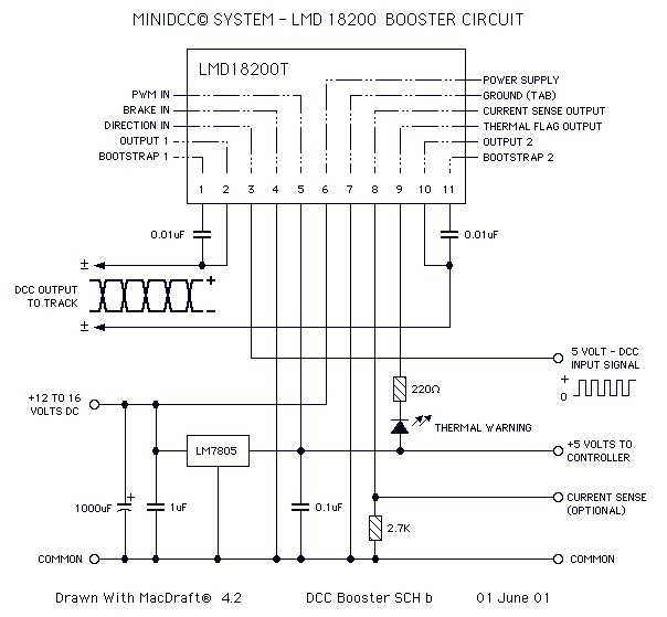
This page features H-Bridge circuits used for controlling direct current motors. Several designs are shown using both CMOS and Bi-Polar power devices. These circuits could be used as the basis for Model Railroad DCC Boosters or PWM motor controllers....
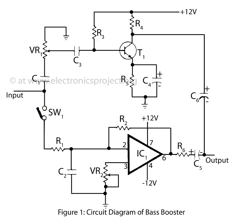
The bass booster featured on this website enhances the beat frequency while maintaining the integrity of the high-frequency response. The circuit diagram for the bass booster, along with various radio circuits, is also provided. The bass booster circuit operates by...
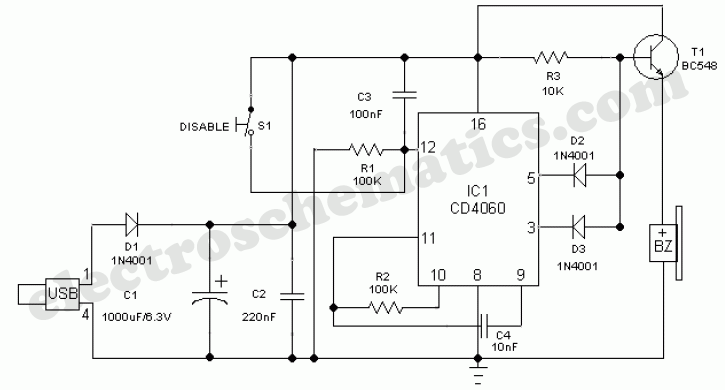
This simple circuit can be used to protect a bike from theft. It produces a loud alarm tone if someone attempts to start the bike. The alarm can only be disabled when the hidden switch S2 is opened. The...

This optodetector measures the position of the ball by the amount of light transmitted by the infrared LED. It generates a linear signal across the small area of the detector, rather than simply providing an "on" or "off" output....
The Pulse Demodulator, as illustrated in the accompanying image, consists of a CMOS Hex Inverter. This circuit is capable of performing envelope detection on amplitude pulses. The Pulse Demodulator utilizing a CMOS Hex Inverter is designed to extract the envelope...