
220V live wire-in-wall scanner

The described circuit functions as a non-contact voltage detector, utilizing a capacitive sensing mechanism to identify the presence of an AC voltage source, specifically a 220V live wire. The core components of the circuit include a Field Effect Transistor (FET), a capacitive metal sensor, an LED indicator, and a power supply of 9V DC.
The capacitive metal sensor acts as the sensing element, detecting changes in the electric field caused by the presence of the live wire. When the sensor is brought near the wall, the electric field around the 220V wire influences the gate of the FET. The FET is configured in such a way that it turns on in response to the capacitive coupling from the sensor, allowing current to flow through the LED.
The LED serves as a visual indicator, illuminating when the FET is activated by the detected electric field, thus signaling the presence of the live wire. The circuit is powered by a 9V DC supply, which is necessary to ensure that the FET operates within its optimal range.
In terms of circuit design, appropriate resistors may be included to limit the current through the LED and to set the gate threshold of the FET. Additionally, a capacitor could be placed in parallel with the FET to filter out any noise and enhance the stability of the detection signal.
This circuit is particularly useful for electricians and DIY enthusiasts who need a safe method to locate live wires behind walls without direct contact. It is important to note that while this circuit can indicate the presence of voltage, it does not provide information about the current or the specific characteristics of the electrical system. Proper safety precautions should always be observed when working around live electrical circuits.This little circuit will help you to scan the line of a 220V live wire in the wall. The FET gate is connected to a capacitive metal sensor (which is usually a simple metal plate). When you hold the sensor close to the wall, the LED will indicate the current flow around where it detects the wire. Works on 9VDC. 🔗 External reference
Related Circuits
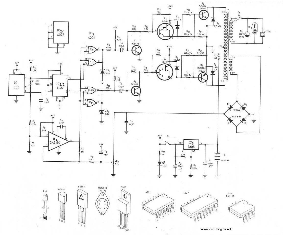
12V to 220V inverter circuit diagram, 24V inverter circuit, 24V to 220V inverter, 24VDC to 220VDC, 300W inverter, 300W inverter circuit diagram, inverter, inverter 24V to 220V, inverter circuit, inverter DC to AC, power electronics. The inverter circuits mentioned are...

This electronic device functions similarly to a metal detector but has a unique capability: it detects live electrical wires. This gadget is particularly beneficial for electricians engaged in repair or renovation tasks. The ability to locate hidden wires significantly...

This 220V mains operated solid-state flashing lamp circuit utilizes a 555 timer integrated circuit (IC) to manage the ON and OFF durations of a triac that regulates power to the load. The circuit operates at a mains voltage of 220V,...

A stabilized voltage inverter that converts 12V to 220V with a power rating of 200W is illustrated in the accompanying diagram. This inverter can utilize an existing dual 12V-200W mains transformer; however, it exhibits low inverter efficiency. The described stabilized...

This DIY 12V to 220V voltage converter is built with a CMOS 4047, which serves as the main component of this compact voltage converter that transforms 12V DC into 220V AC. The 4047 functions as an astable multivibrator; at...

This circuit is designed to convert 12V DC into 220V AC. It utilizes a 4047 integrated circuit to generate a 50Hz square wave, which is then amplified for current and voltage using a step-up transformer. The fundamental relationship between...