
220V Touch Switch circuit diagram

The circuit operates by interfacing directly with the 220V AC mains supply, which is a standard voltage level in many residential electrical systems. The LOAD component, as indicated in the schematic, is designed to operate at this voltage and is responsible for performing a specific function, such as lighting, heating, or powering other electronic devices.
To ensure safe operation, the circuit should incorporate protective devices such as fuses or circuit breakers, which will interrupt the current flow in the event of an overload or short circuit. Additionally, the use of properly rated wiring is essential to handle the current without overheating, which could lead to fire hazards.
The schematic may also include a switch to control the power to the LOAD, allowing for manual operation. Furthermore, if the application requires, a relay could be integrated into the design to enable remote control or automation of the LOAD, enhancing convenience and functionality.
Proper grounding practices must be followed to minimize the risk of electric shock and to ensure the stability of the circuit. The design should adhere to relevant electrical codes and standards to guarantee safety and reliability in operation.This circuit is connected directly to a 220V home electrical installations. LOAD on the schematic diagram above, is an electronic device with 220V AC current consumption. 🔗 External reference
Related Circuits
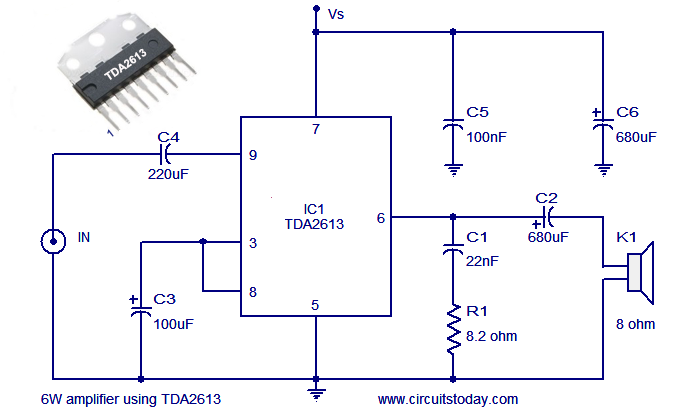
A simple and easy-to-build Hi-Fi audio power amplifier circuit is presented here. This 6-watt Hi-Fi audio amplifier circuit utilizes the TDA2613 integrated circuit (IC). The circuit design employs the TDA2613, which is a high-performance audio amplifier IC known for its efficiency...

Uploaded with ImageShack.us Uploaded with ImageShack.us Uploaded with ImageShack.us Inquiry regarding experiences with specific circuits. In this context, the inquiry pertains to the performance and functionality of certain electronic circuits that have been shared via an image hosting service. The...
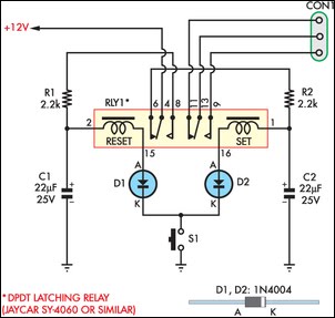
This circuit enables an SPST momentary pushbutton to function as a push-on, push-off switch by utilizing a DPDT latching (bi-stable) relay. It was designed to allow a single pushbutton switch on the dashboard of a vintage car to provide...
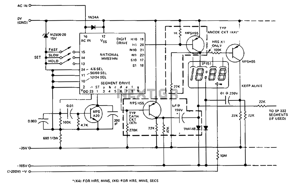
A CMOS clock circuit is capable of driving a multi-digit gas discharge display. This simple circuit does not include an alarm feature but allows for a flashing colon to indicate morning and afternoon. The circuit requires seven drive circuits...
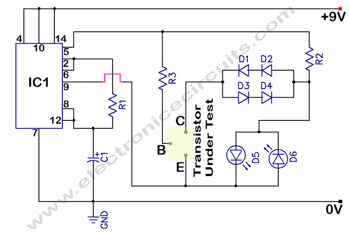
The circuit is a transistor tester schematic that indicates the condition of a transistor using two LEDs. It is designed to test a good NPN transistor. The transistor tester circuit operates by utilizing two light-emitting diodes (LEDs) to provide a...
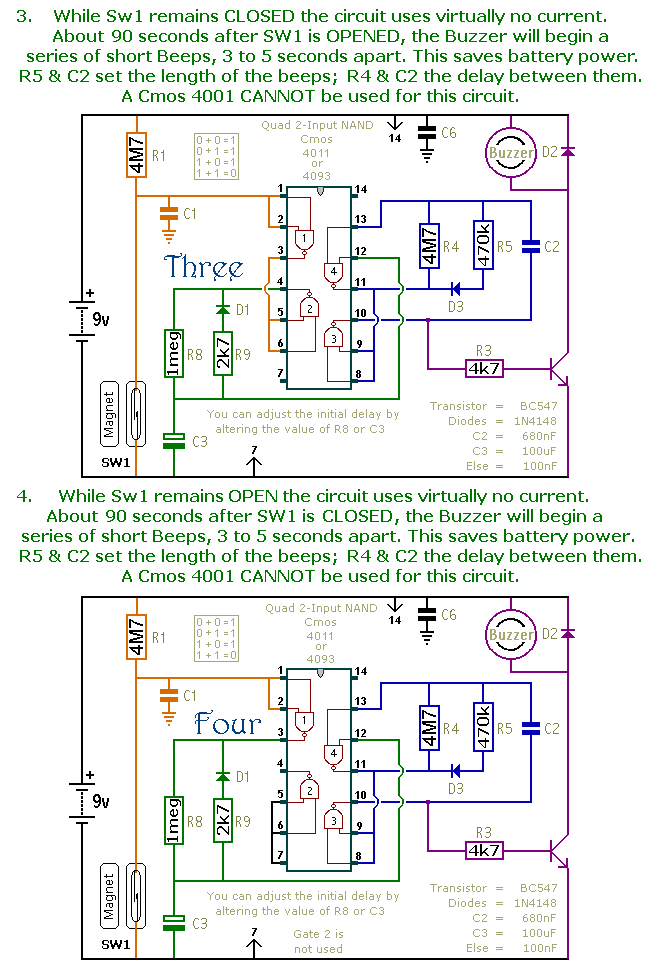
This document presents a collection of compact, self-contained alarm circuits. These circuits are designed to operate with a very low standby current, making them ideal for battery-powered applications. They can be triggered by both normally-open and normally-closed switches, while...