
In-Circuit Transistor Tester

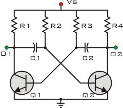
The transistor tester circuit operates by utilizing two light-emitting diodes (LEDs) to provide a visual indication of the transistor's functionality. The circuit typically incorporates a power supply, resistors, and a few other passive components to ensure proper operation.
When an NPN transistor is inserted into the designated socket of the circuit, the tester applies a small current through the base of the transistor. If the transistor is functioning correctly, it will allow a larger current to flow from the collector to the emitter, illuminating one of the LEDs, which indicates that the transistor is in good condition.
In contrast, if the transistor is faulty or damaged, the circuit will not allow the current to flow effectively, resulting in the other LED lighting up or no LEDs lighting at all. This simple yet effective design enables users to quickly determine the operational status of NPN transistors without the need for complex testing equipment.
The circuit can be enhanced with additional features such as a switch to select between testing NPN and PNP transistors, or the inclusion of a digital display for more precise readings. Furthermore, incorporating a variable resistor can allow adjustments to the current applied to the base, accommodating different transistor specifications. Overall, this transistor tester circuit provides an efficient and straightforward method for evaluating the health of transistors in various electronic applications.In Circuit Transistor Tester Schematic Here is a circuit that can indicate the condition of a transistor by using two LEDs. A good NPN transistor. 🔗 External reference
Related Circuits
This circuit is designed to drive a relay coil using a low power output, typically from an integrated circuit (IC) such as a 555 timer or a TTL/CMOS device. It facilitates the switching of high loads or loads requiring...

The power supply varies, and the circuit must operate at under 10 µA of current (excluding the capacitor charging). It triggers a Silicon Controlled Rectifier (SCR) every 10 to 30 seconds as long as the power supply is above...
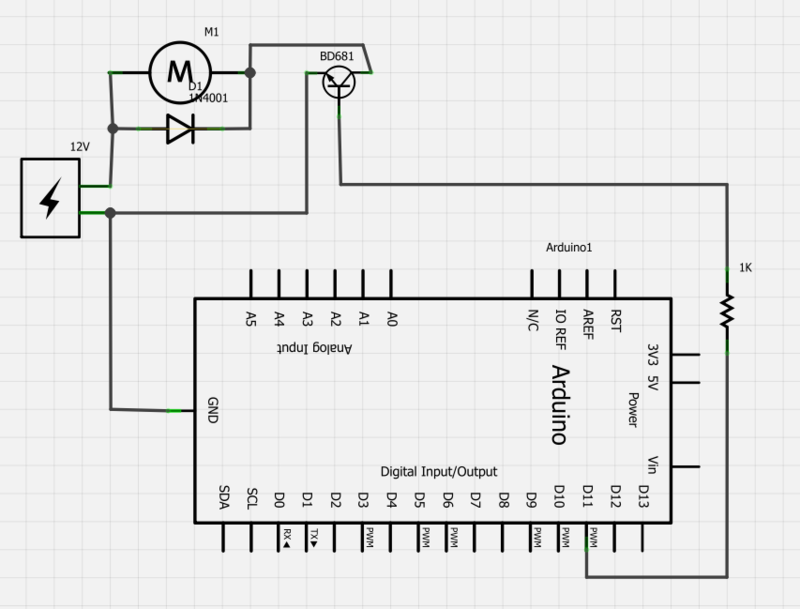
Power a 12V fan using a Darlington transistor to control the speed from an Arduino. When wired as described, nothing happens even though a PWM signal is being sent. It is suggested to edit the question and ensure the...
Liquid crystal displays (LCDs) are available in various versions and sizes. The wide variety of features has led to some confusion regarding pin configurations. Consequently, even after extensive searching for a suitable screen, users often encounter difficulties in utilizing...
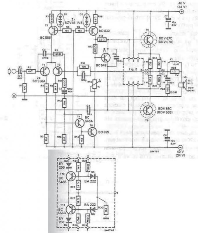
A high-power audio amplifier can be designed using power transistors and other common electronic components, capable of delivering a maximum output power of 90W. When using the specified component values, it can drive speakers with a 4-ohm impedance, resulting...
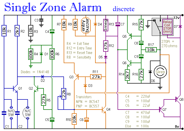
The circuit includes automatic exit and entry delays, a timed bell cut-off, and a system reset feature. It accommodates both normally-open and normally-closed switches, making it compatible with standard input devices such as pressure mats, magnetic reed contacts, foil...