
Four gas monitor circuit diagram

The CMOS clock circuit operates using complementary metal-oxide-semiconductor technology, which is known for its low power consumption and high noise immunity. The design includes a multi-digit gas discharge display, where each digit is illuminated by gas discharge, providing a bright and clear visual output.
The circuit's simplicity lies in its ability to manage the display without complex components or features. The flashing colon serves as a visual indicator for AM and PM, enhancing the functionality of the clock without the need for an alarm system.
In terms of the driving circuits, seven are required to properly manage the display, with the digital driver circuit playing a crucial role in controlling the operation of the gas discharge display. Although only two circuits are actively used for displaying the time, the additional circuits are essential for ensuring that the display operates correctly and can handle the necessary voltage and current levels.
For applications requiring the display of seconds, an extra drive circuit is mandated. This additional circuit allows for the integration of a second display or the enhancement of the existing display to show seconds alongside hours and minutes.
Overall, the CMOS clock circuit is an effective solution for timekeeping applications that require a simple yet functional display system. Its design ensures reliability and ease of implementation, making it suitable for various electronic projects. CMOS clock circuit can drive a multi-digit gas discharge display, simple circuit does not include an alarm, which can be flashing colon morning and afternoon show. The circuit need to use seven drive circuits and digital driver circuit, although only display two circuits among a. If you want to display seconds, then you will also need an additional drive.
Related Circuits
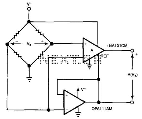
For systems with a single power supply, two operational amplifiers function as instrumentation and buffer amplifiers. The OPA111 AM buffers the reference mode of the bridge and applies that voltage to the reference terminal of the instrumentation amplifiers. The...
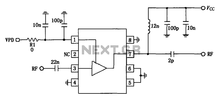
836MHz RF2347 low noise amplifier circuit diagram. The RF2347 is a low noise amplifier (LNA) designed for operation at a frequency of 836 MHz. It is typically used in RF applications where signal amplification is critical, such as in communication...
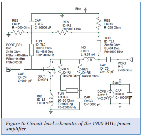
Achieving optimal performance from circuits used in third- and fourth-generation wireless systems necessitates tighter integration of previously separate tools. A degree of software synergy is crucial when designing circuits for modern wireless systems that utilize advanced modulation techniques alongside...
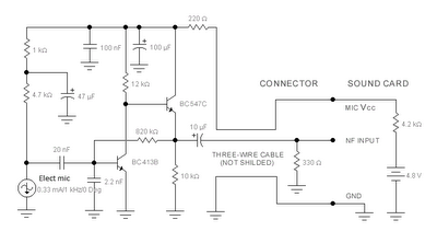
The sound card for a PC typically includes a microphone input, speaker output, and occasionally line inputs and outputs. The microphone input is specifically designed for dynamic microphones with an impedance range of 200 to 600 ohms. An adaptation...
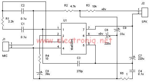
A very simple audio amplifier circuit can be designed using the TBA820M audio amplifier integrated circuit with just a few electronic components. This audio amplifier project features a high gain that allows for the detection of sounds underwater. The...
The PWM circuit is causing the inverter's current consumption to reach a dangerous level of 14 Amps. A potential solution involves reducing the drive voltage to the gates of the MOSFETs by controlling the base voltage of the buffer...