
Need Help: Wiring LEDs with 2 source voltages

To achieve the desired functionality of displaying two brightness levels for the LED lights, a dual-resistor approach can be employed. The circuit should include a pair of series-connected LEDs, each rated for a forward voltage of 1.1V and a forward current of 75mA. When connected in series, the total forward voltage drop across the two LEDs will be 2.2V, while the current flow through the circuit will remain at 75mA.
To implement the two brightness levels, a switching mechanism can be introduced. This can be accomplished using a transistor or a MOSFET, which will allow for the control of current flowing through the LEDs. In the first brightness level, the full current of 75mA can be allowed to flow, while in the second brightness level, a resistor can be placed in series with the LEDs to reduce the current, thereby dimming the lights.
For the resistor calculation, the desired current for the dimmed state should be established. For example, if the target current for the dimmed state is 37.5mA, the series resistor can be calculated using Ohm's Law. The voltage across the resistor can be determined by taking the difference between the source voltage and the total forward voltage of the LEDs (2.2V).
If a 5V supply is used, the voltage across the resistor would be 5V - 2.2V = 2.8V. The required resistance to achieve 37.5mA can be calculated as follows: R = V/I = 2.8V / 0.0375A = 74.67 ohms. A standard resistor value of 75 ohms can be selected.
In summary, the circuit will consist of two series LEDs, a switching mechanism to alternate between brightness levels, and a series resistor for the dimmed state. Proper attention should be given to the power ratings of the components to ensure safe operation. The power rating for the resistor can be calculated using P = I^2 * R, which should exceed the calculated power to prevent overheating. This design will effectively provide the desired functionality for additional running lights and brake lights on the bicycle.A series of LEDs I would like to have display at 2 brightness levels and am confused how to properly wire this. This is for additional running lights/brake lights on my bike. When using the series LED calculator I believe for the Source voltage 1 I should set the forward voltage to 1.
1V and 75ma (half of typical voltage and half of forwardcurrent) and then set the Source Voltage 2 to 1. 1V and 75ma (the other half of voltage and forward current). That in my eyes would result 2. 2V and 150ma. 🔗 External reference
Related Circuits
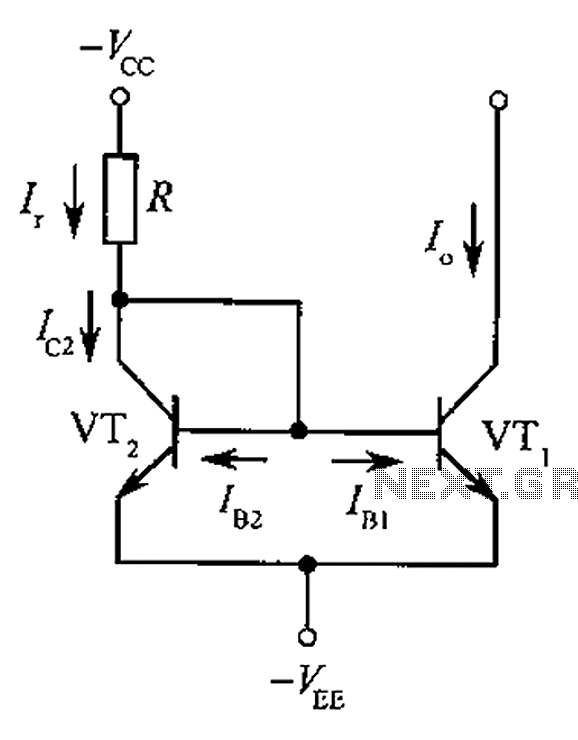
The circuit depicted is a mirror substantially constant current source circuit, in which transistors VT1 and VT2 are matched to each other. The figure illustrates that the current through Ir is equal to Ic2 plus the sum of base...
The wiring diagram for the 1986 Honda Civic includes components such as the neutral switch, automatic choke heater, charge warning light, resistor, starter motor, starter solenoid, thermo switch, regulator, alternator, distributor, igniter, ignition coil, spark plugs, and air temperature...
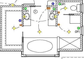
The following circuit illustrates the installation of a bathroom electrical wiring circuit diagram. Features include safety, energy savings, and enhancement of home functionality. This circuit diagram provides a comprehensive overview of the electrical wiring necessary for a bathroom installation. It...
The circuit shown demonstrates how to power one or two LEDs from a 120-volt AC line by utilizing a capacitor to reduce the voltage and a small resistor to limit the inrush current. Because the capacitor needs to conduct...
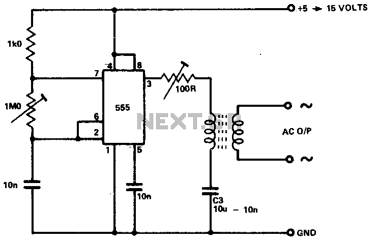
The circuit is designed to supply power for portable Geiger counters, dosimeter chargers, high resistance meters, and similar devices. The 555 timer integrated circuit (IC) operates in its multivibrator mode, with the frequency adjusted to optimize the characteristics of...
A simple LED-based voltmeter is required to monitor the voltage of a variable power supply. The proposed LED voltmeter circuit utilizes a series of light-emitting diodes (LEDs) to visually represent the voltage level of a variable power supply. This...