
24hr clock using logic ics

The circuit described is based on a decade counter, typically implemented with a 4017 decade counter IC, which counts from 0 to 9 in response to clock pulses. The clock input is essential for advancing the count, and the rising edge of the clock signal triggers the counting action. Outputs Q0 through Q9 are used to indicate the current count, activating sequentially with each clock pulse. The use of diodes to combine outputs for specific sequences allows for flexible applications, such as creating visual effects with LED displays.
The reset function is critical for initializing the counter or for setting specific counting ranges. By connecting an output to the reset pin, the counting can be limited, allowing for applications that do not require a full decade count. The disable input serves as a control mechanism to pause counting, which can be useful in scenarios where the count needs to be held constant temporarily.
The G·10 output is particularly useful for cascading multiple counters, enabling the design of more complex counting systems. This output effectively divides the clock frequency by ten, making it suitable for driving additional decade counters.
The display control inputs—enable display and disable clock—provide user control over the visibility of the count and the counting process itself. These features enhance the versatility of the circuit, allowing it to be adapted for various applications, including digital clocks, scoreboards, and other counting devices.
In summary, this circuit provides a robust solution for counting applications, featuring multiple control inputs for flexible operation, and is capable of driving displays directly, making it suitable for a wide range of electronic projects.The count advances as the clock input becomes high (on the rising-edge). Each output Q0-Q9 goes high in turn as counting advances. For some functions (such as flash sequences) outputs may be combined using diodes. The reset input should be low (0V) for normal operation (counting 0-9). When high it resets the count to zero (Q0 high). This can be do ne manually with a switch between reset and +Vs and a 10k resistor between reset and 0V. Counting to less than 9 is achieved by connecting the relevant output (Q0-Q9) to reset, for example to count 0, 1, 2, 3 connect Q4 to reset. The disable input should be low (0V) for normal operation. When high it disables counting so that clock pulses are ignored and the count is kept constant. The G·10 output is high for counts 0-4 and low for 5-9, so it provides an output at 1/10 of the clock frequency.
It can be used to drive the clock input of another 4017 (to count the tens). The count advances as the clock input becomes high (on the rising-edge). The outputs a-g go high to light the appropriate segments of a common-cathode 7-segment display as the count advances. The maximum output current is about 1mA with a 4. 5V supply and 4mA with a 9V supply. This is sufficient to directly drive many 7-segment LED displays. The table below shows the segment sequence in detail. The disable clock input should be low (0V) for normal operation. When high it disables counting so that clock pulses are ignored and the count is kept constant. The enable display input should be high (+Vs) for normal operation. When low it makes outputs a-g low, giving a blank display. The enable out follows this input but with a brief delay. The G·10 output (h in table) is high for counts 0-4 and low for 5-9, so it provides an output at 1/10 of the clock frequency.
It can be used to drive the clock input of another 4026 to provide multi-digit counting. 🔗 External reference
Related Circuits
The simplest method of detecting metal is through a beat frequency oscillator. The circuit consists of two balanced oscillators: one serves as the detector element while the other provides a reference signal. The reference oscillator frequency is set to...
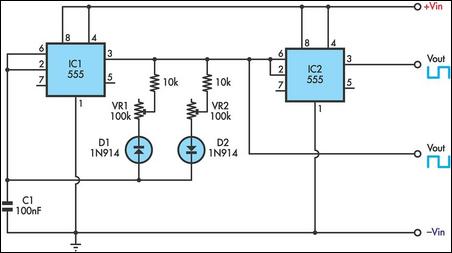
This timer utilizes two 555 integrated circuits (ICs) to adjust the desired output. The variable resistors VR1 and VR2 serve as potentiometers to modify the cycle speed. The circuit can be powered with a 9 to 12-volt power supply,...
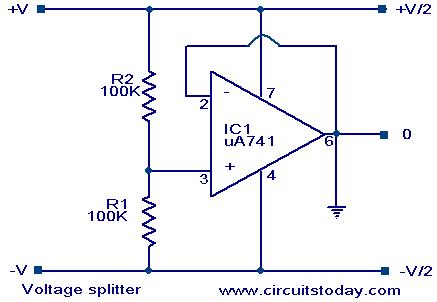
Voltage splitter using op-amp uA741 IC, circuit diagram, working, description. The voltage splitter circuit utilizing the uA741 operational amplifier (op-amp) is designed to provide a stable output voltage that is a fraction of the input voltage. The uA741 is a...

A motor spins the propeller, while a small microprocessor tracks time and alters the pattern on seven LEDs with precise timing to create the illusion of a 7 by 30 array of LEDs. This concept, initially developed by Bob...
This simple circuit combines two or more audio channels into a single channel (for example, mixing stereo into mono). The circuit is capable of mixing an arbitrary number of channels while consuming minimal power. Although the schematic illustrates two...
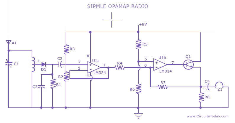
A low-cost, simple radio circuit schematic using an operational amplifier. This radio circuit diagram consists of a sensitive audio amplifier that receives strong signals. The presented radio circuit schematic utilizes an operational amplifier (op-amp) to create a cost-effective and straightforward...