
propeller clock amazing illusion

The propeller clock operates on the principle of persistence of vision, where the rapid movement of the propeller combined with the synchronized illumination of the LEDs creates a visual effect that tricks the human eye into perceiving static images. The motor is typically a brushless DC motor, selected for its efficiency and ability to maintain a constant speed, which is crucial for the accurate timing necessary for the illusion to work effectively.
The PIC microcontroller is programmed with a specific algorithm that determines the timing of each LED based on the rotational speed of the propeller. The microcontroller receives input from the photo detectors, which detect the position of the propeller blades and provide feedback to ensure that the LEDs light up at the correct moment. The use of photo detectors minimizes the impact on the visual appearance of the clock, as they are discreetly placed and do not interfere with the spinning propeller's aesthetics.
The clock features multiple modes, including a digital display mode that shows numerical time and an analog mode that simulates clock hands. Users can switch between these modes through a user interface that may consist of buttons or touch sensors, designed to be accessible even while the clock is in motion. This innovative design not only enhances user experience but also showcases the advanced engineering involved in creating a visually captivating timepiece.
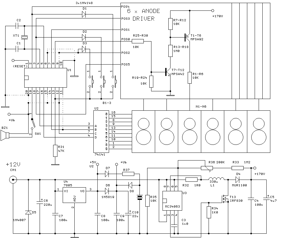
Overall, the propeller clock exemplifies a blend of mechanical and electronic engineering, demonstrating how precise timing, sensor integration, and visual effects can create an engaging and functional device.A motor spins the "propeller", and a small microprocessor keeps track of time and changes the pattern on seven LEDs with exact timing to simulate a 7 by 30 array of LEDs. It is an illusion, but it works nicely. Propeller clocks were to my knowledge first started by Bob Blick then many people started copying his idea and adding certain improvements
along the way. Propclocks are really pretty complex devices, utilizing a PIC microcomputer that performs instructions at 10mhz. The PIC is the brain of the device and does most of the work involved in making the LEDs light up at just the right time so that it appears there are numbers, and in the analog mode hands suspened in mid air.
On my version of the clock you change the mode and time setting while it is still spinning at about 1150 PRM. This is done through carefully alligned photo detectors and LEDs. These sensors are located on the rear of the spinning motor so they dont affect the look of the clock at all.
🔗 External reference
Related Circuits
A clock-and-data recovery (CDR) circuit is utilized to recover the clock from a transmitted data stream and re-time that data with the recovered clock. These circuits are generally positioned at the front-end of receiver chips to extract the clock...
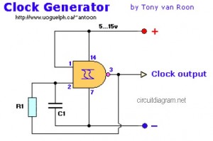
The following diagram represents a Clock Generator circuit that is constructed using NAND Gate logic integrated circuits (ICs). The circuit can utilize either IC 7400 or IC 4011. The 7400 is a TTL (Transistor-Transistor Logic) type, whereas the 4011...
A beep or metronome-like click and/or a visible flash will indicate a one-second interval, which can be useful in various applications requiring time-delay counting in seconds. The circuit utilizes a CMOS 4024 counter/divider chip and three diodes, configured to...
To initiate the process, the LOAD switch and Reset switch must be pressed simultaneously within 24 seconds; otherwise, the countdown will commence from 99. A pulse input can be connected to a 555 astable multivibrator, but it must be...
The clock will have 6 digits and time setting will be done by means of a few buttons. I will try to use the most common types from widely used microcontroller families of miscellaneous producers. I will write the...
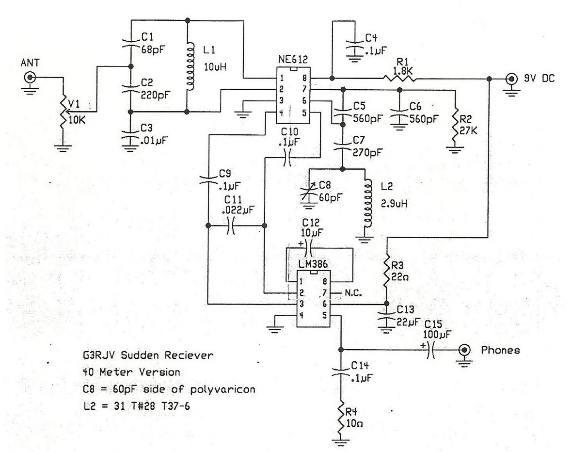
A straightforward direct conversion receiver utilizes the NE602 Gilbert Cell mixer and an LM386 audio amplifier. This circuit is inspired by the well-known sudden receiver design from Rev. George Dobbs, G3RJV. The implementation omits the tuned circuit components connected...