
24V Battery Charger Schematic

Additionally, a 24V 7A battery charger is being developed, but similar issues have arisen with the use of an IRF250 transistor and a 0.1-ohm resistor. Questions have been raised regarding the power rating of the resistor. There is also a need for a power supply to operate a 24V 5A electric motor sourced from an old mobility scooter, with an interest in building a custom power supply. Queries include whether the same inverter transformer can be used for charging and if a 450-ohm resistor can be replaced with a 470-ohm resistor. Furthermore, a request has been made for a circuit diagram to integrate the 24V battery charger into the inverter circuit, utilizing the inverter transformer with 24V-0-24V taps for charging a 24V battery.
Several technical questions have been posed regarding the operation of U1 and U2, particularly concerning the isolation provided by diode D1 and the implications for Q1's behavior in both the current limiting and float charge stages. Clarifications are sought on whether the voltage drop across a 20K resistor (R2) should be considered in conjunction with R1, as even a low current could result in a significant voltage drop. Additionally, assumptions regarding the charging time for a 24V battery with a capacity of 100-150 Ah have been questioned, particularly concerning the potential charging duration and the behavior of the circuit when connected to the battery without load.
The schematic for this battery charging circuit should include the transformer, rectification components (diodes), filtering capacitors, transistors (U1 and Q1), the sense resistor (R1), and the Zener diode (U2). The transformer steps down the AC voltage to a lower level suitable for battery charging. The rectification stage converts AC to DC, which is then filtered to smooth the output voltage. The control circuitry, including the transistors and resistors, regulates the charging process by limiting current during the initial charging phase and transitioning to a float charge mode once the battery reaches a predetermined voltage. The inclusion of the Zener diode allows for voltage regulation during the float charge stage, ensuring that the battery is maintained at an optimal voltage without overcharging.
This circuit can be customized to accommodate various battery types and capacities, with careful attention to component ratings to ensure reliable operation. The design should also include protective measures against overcurrent and overvoltage conditions to enhance safety and longevity of the charging system.240/24Vac(rms) transformer was used. After rectification and filtration i got about 30Vdc. Therefore the transformer and diode rating should be well chosen to meet your demand At the current limiting stage, transistor U1, Q1 and resistor R1 plays the vital roll in the current limiting; When U1 switches on it short circuits the gatevoltage of Q1 thereby restricting current flow through the battery under charge. U1 will only switch when Voltage across it`s base-emitter Vbe is up to 0. 7V. the voltage drop across R1 determine this, if the voltage drop across R1 is up to 0. 7V then U1 switches on then, I(current thru batt)=0. 7/R1(sense resistor). Ohms Law. The float charge stage come to play when the Battery Voltage builts up to 28Vdc. In this design once the voltage gets to 28Vdc, it is considerably large enough to make the zener diode reach it breakdown voltage. And once this is done U2 switches on and consequently short circuit gate voltage of Q1. The charger is now said to float charge. i am also make a 24v 7amp battery charger but i have also same problem i am using irf250. also r1 0. 1om how many wats resister using please sent me replay about this problem in my gmail account. I have a DC 24v 5amp electric motor taken from an old mobility scooter that had been powered by lead-acid batteries.
I need a power supply to run off the mains to drive this motor for a new application. I would like to build my own power supply therefore can I use something like the 24v charger designed by `maxolous` hi sir i want to build this charger but i have a small problem can i use the same inverter transf to charge and can i replays 450 ohms resister with 470 ohms hi sir i want to build this charger but i have a small problem can i use the same inverter transf to charge and can i replays 450 ohms resister with 470 ohms please, can you send to my mail a circuit diagram of how to incorporate this 24 volt battery charger you design into your inverter circuit diagram to be able to use the inverter transformer to 24v-0-24v tapping to charge the 24volts battery. my mail is adewale012@yahoo. com. Thank you very much. Please I am still expecting your reply. God bless you. please, can you send to my mail a circuit diagram of how to incorporate this 24 volt battery charger you design into your inverter circuit diagram to be able to use the inverter transformer to 24v-0-24v tapping to charge the 24volts battery.
my mail is adewale012@yahoo. com. Thank you very much. 1. You mentioned that during float charge stage U2 switches on and short circuits gate voltage of Q1 - but there is a diode D1 which is isolating base of Q1 from U2 and so how will U2 short circuit Q1 2. Also, in current limiting stage U1 shorted the Q1 gate and in float charge stage U2 has shorted the Q1 gate.
Then I would expect Q1 to behave in the same manner in both phases. Please help me understand here. Thanks I have one more question. In your notes aobe you have mentioned that U1`s Vbe will be 0, 7 if the volatage drop across R1 is 0. 7 volts. Should we not add the voltage drop across R2 which is 20K and even a low current will give significant voltage drop.
3. In your circuit you have indicated R1 to be 0. 1 Ohm. So using the formular 07. /0. 1 gives 7 AMPs. I am assuming the 24V battery is 100-150 AMPh. If 50% of the available power is drained, then the battery will take 7- 11 hours to charge. Is this calculation correct If I plug it in before connect it to the battery, it will not charge it. I guess because the input voltage is about 30-33V without load. Do I miss something There are so many ways you can achieve this, the simplest is to put LED across the charging terminals, also put a 2k2 resistor in series with the LED to limit current. you will observe that when it is not charging the LED will not glow reason is that MOSFE 🔗 External reference
Related Circuits
Many later radios utilize four 7-pin valves and require a high tension (HT) supply of 90V at approximately 12mA, and a low tension (LT) supply of either 125mA or 250mA, depending on the specific valves used. The original batteries...
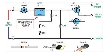
Although smoke alarms are relatively inexpensive devices, the cost of 9V batteries can quickly surpass their initial purchase price. Additionally, the annoyance of random beeping can be a significant drawback. Smoke alarms are essential safety devices designed to detect smoke...
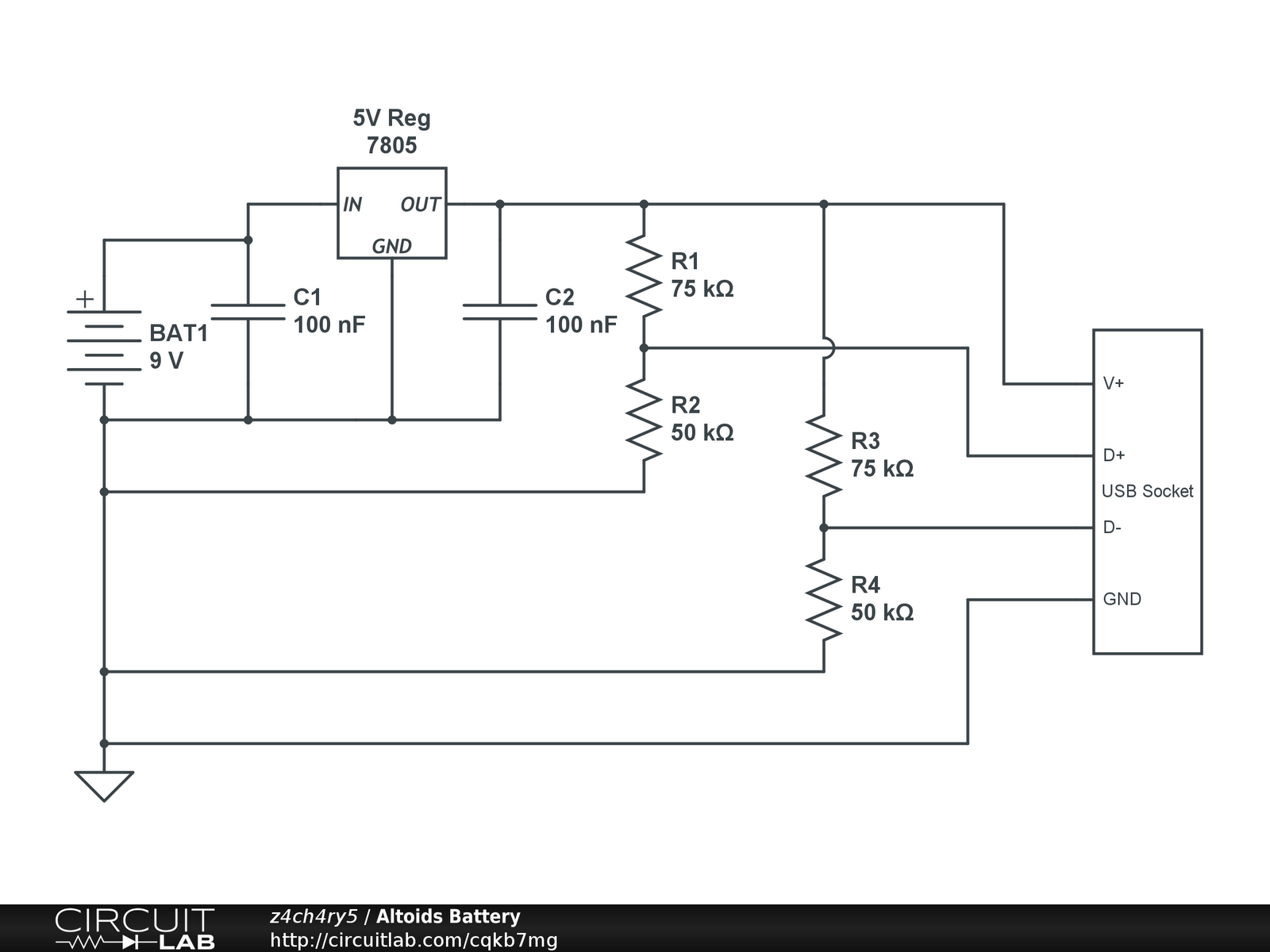
Instructions for creating a battery pack for Apple devices powered by standard alkaline batteries are provided. This overview outlines the circuit design for the battery pack, with detailed casing instructions to follow in a subsequent section. Note: When soldering...
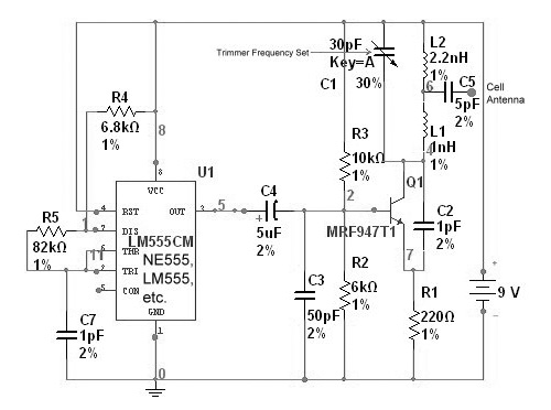
The circuit is based on the NE555 timer, functioning as a simple noise maker, with its output connected to a single transistor oscillator. This oscillator is designed to operate within a frequency range of 800 MHz to 2 GHz,...
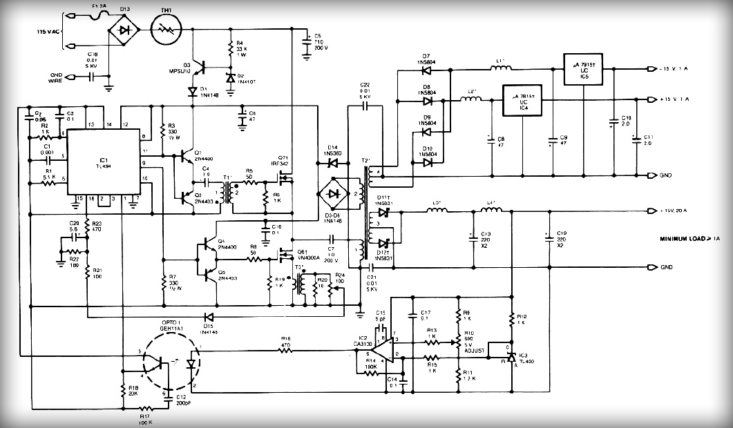
This power supply employs two VN400A 400-Volt MOSFETs arranged in a half-bridge configuration. The outputs provide +5V at 20A and +15V at 1A. Low-current outputs utilize three-terminal regulators, allowing for either 12 Volts or 15 Volts to be achieved...
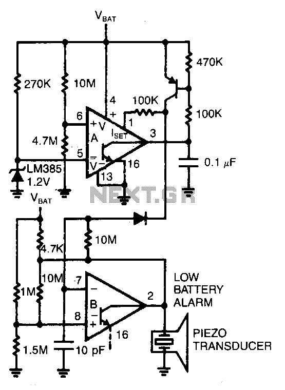
Comparator A detects when the supply voltage drops to 4 V and enables comparator B to drive a piezoelectric alarm. More: Is: 6V at 45μA, Is: 3.8V at 1μA, f: 3kHz The circuit utilizes two comparators to monitor supply voltage...