
24v to 12v converter

The 24V to 12V converter circuit typically employs a linear regulator or a switching regulator topology to achieve the desired voltage conversion. In a linear regulator configuration, a series pass transistor is used to drop the excess voltage while maintaining a stable output. This method is simple but can be inefficient due to power dissipation across the transistor, especially under high load conditions. Therefore, proper heat sinking is essential to prevent thermal failure.
In contrast, a switching regulator utilizes pulse-width modulation (PWM) techniques to efficiently convert voltage by switching the input voltage on and off rapidly. This method significantly reduces heat generation, allowing for a more compact design without the need for extensive heat dissipation measures. Key components in a switching regulator circuit include an inductor, a diode, and a capacitor, which work together to smooth out the output voltage.
Regardless of the design choice, it is crucial to ensure that all components are rated for the expected current and voltage levels. Proper insulation of components from metal chassis is also necessary to prevent short circuits and ensure reliability. The layout of the circuit should minimize the length of high-current paths to reduce inductance and potential voltage drops.
For both linear and switching designs, the input and output capacitors play a vital role in stabilizing the voltage and filtering out noise. It is advisable to use low equivalent series resistance (ESR) capacitors for improved performance. Additionally, implementing protection features such as overcurrent protection and thermal shutdown can enhance the robustness of the converter circuit.
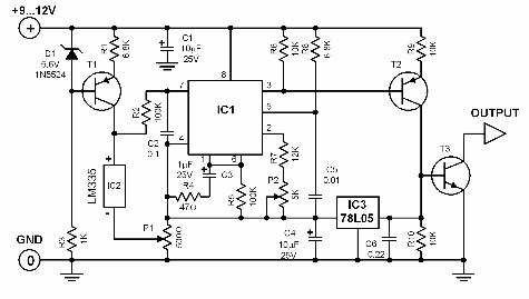
In summary, whether using a linear or switching approach, careful consideration of component selection, thermal management, and circuit layout is essential for the successful implementation of a 24V to 12V converter.The 24v to 12v converter schematic is very simple but remember all the components (transistors and integrated) should be given with good heat dissipation and electrically insulated from the metal. The schematic diagram come from circuit: 24v to 12v converter power supply. Go to that page to read the explanation about above power supply related ci rcuit diagram. 🔗 External reference
Related Circuits
In certain temperature measurement applications, converting the measured value into a frequency rather than a voltage offers distinct advantages. A temperature-to-frequency converter can be directly interfaced with a frequency counter or connected to a computer without necessitating an A/D...
Many times we needed a variety of voltages, from a battery 12V. With the circuit, we can take voltages smaller or bigger, positive or negative, from a battery 12V. The idea is based in oscillator roughly 7KHZ, round the...
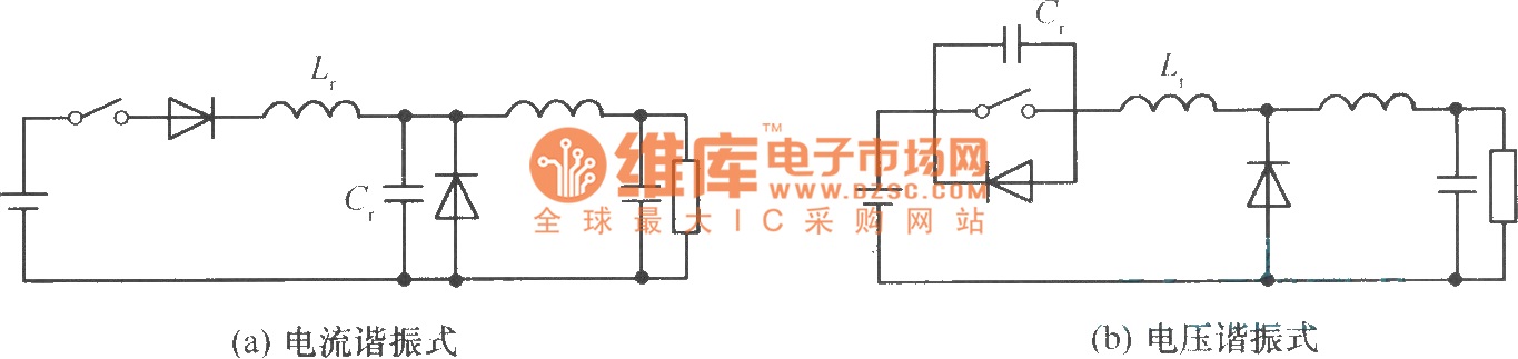
In a commonly used switching stabilized voltage supply, a resonant switch can be utilized to replace the shape of a step-down converter, resulting in a resonant converter circuit. The diagram illustrates the transformation from a step-down converter to a...
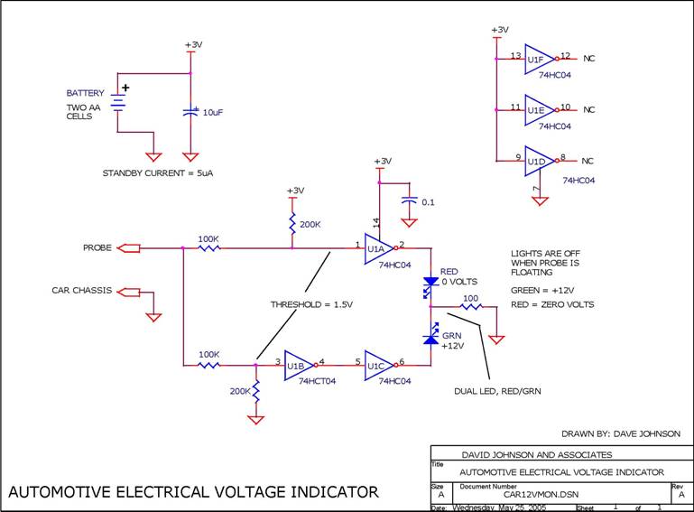
When troubleshooting the 12V electrical system of an automobile, it is beneficial to have a simple voltage indicator tool instead of a voltmeter. This electronic circuit is powered by two AA batteries or two N cells, providing sufficient energy...
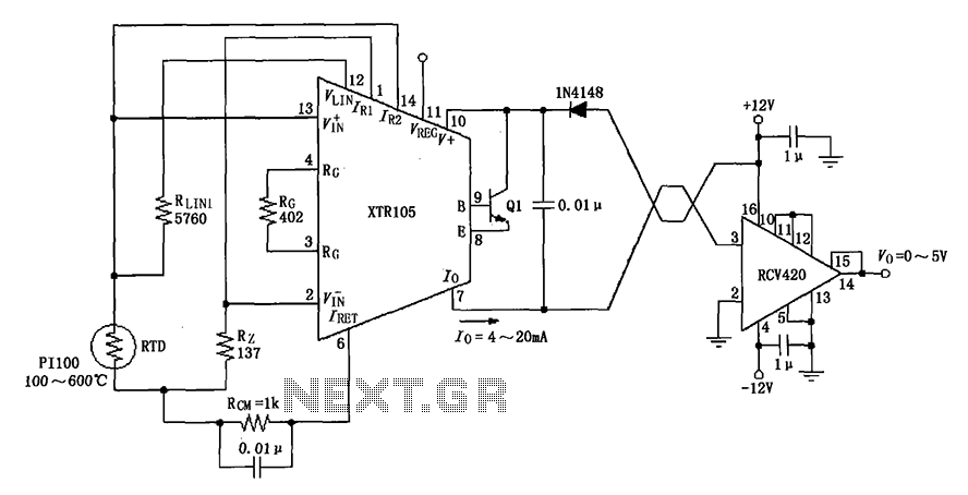
The circuit utilizes a Pt100 type resistance temperature detector (RTD). It operates within a temperature range of 100 to 600 °C, where the XTR105 outputs a current of 4 to 20 mA, and the RCV420 provides an output voltage...
The VGA-to-Scope converter schematic has been simplified by removing op-amp buffers and inverters. A 1 Megohm potentiometer can be used instead of a continuous current supply to charge the capacitor from a 5V source. Proper placement of the potentiometer...