
25kHz using thyristor inverter welding machine circuit

The thyristor inverter welding machine operates at a frequency of 25kHz, which significantly enhances its efficiency and allows for a more compact transformer design compared to traditional welding machines. The power section is responsible for converting the incoming AC supply into a suitable DC voltage using a series of diodes and filter capacitors to smooth the output.
The inverter section plays a crucial role in converting the DC voltage back into high-frequency AC voltage, which is necessary for effective arc welding. This section utilizes silicon-controlled rectifiers (SCRs) and various passive components to manage the switching and control of the output waveform, ensuring a stable and consistent arc during the welding process.
The flip-flop section provides the necessary pulse signals to drive the inverter, utilizing pulse transformers and RC timing circuits to generate the required switching frequencies. This section is vital for maintaining the high-frequency operation of the inverter and ensuring that the welding process remains efficient.
The output unit is designed to deliver the high-frequency AC voltage to the welding electrode. It consists of a transformer that steps up the voltage as needed, along with diodes that rectify any back EMF generated during the welding process, protecting the circuit from potential damage.
Finally, the arc suppression circuitry is critical for preventing unwanted arcing and ensuring a smooth welding operation. It employs a combination of triacs, thyristors, regulators, diodes, capacitors, and resistors to manage the arc characteristics and maintain a stable welding arc.
Overall, this thyristor inverter welding machine circuit exemplifies advanced design techniques that leverage high-frequency operation for improved performance and reduced size, making it suitable for a variety of welding applications.25kHz using thyristor inverter welding machine circuit Using high frequency 25kHz, thyristor inverter arc welding machine, which can be smaller transformer, the circuit shown i n Figure 9-14. The machine no-load output voltage of 45V DC, 90V (peak), the short-circuit current of 125A DC. Circuit consists of five parts: Power section (by the diode VD16 ~ VD2 [filter capacitor C7 etc.), the inverter section points (by the diode VDi ~ VD4, SCR Vl-V4, resistor Ri-R4, capacitors and inductors Li CL, etc. composition), touch -flop (by a pulse transformer TMi, TMz and associated RC components, diodes, regulator etc.), an output unit divided (by the transformer T and the diode VD22 ~ VD25 etc.) and arc suppression circuitry (by the Triac V5, thyristor V5, the regulator VS3, diode VD, 6, capacitor C8, resistor R14 ~ Rl7 etc.).
Related Circuits
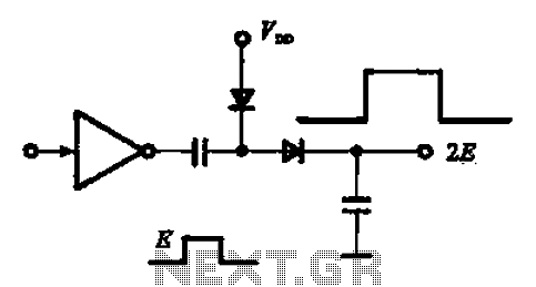
A pulse booster circuit is utilized to increase the pulse amplitude. The structure illustrated in figure (a) of the circuit can output a pulse amplitude that is twice that of the input. Figure (b) of the circuit can achieve...
This is a range of IF signal circuits that may be of interest to radio hobbyists and professionals alike. Transistors T1 and T2 form an astable multivibrator oscillating in the audio frequency range of 1 to 2 kHz. An...
The yellow wires on the far right serve as temporary power connections, allowing battery power to enter through the contact studs located in the large holes that press against the radio's battery terminals. The cable in the lower right...
The circuit illustrates a straightforward triangle and square wave generator utilizing a common dual operational amplifier, the LM1558, capable of producing very low frequencies around 10 kHz. The time interval for one half-cycle is approximately determined by the product...
Upon purchasing the slave dial, it arrived without instructions, packaging, or additional details. The only visible markings, aside from decades of grime, were on the face (SMITH SECTRIC, ACELEC SYDNEY) and some markings on the bracket holding the mechanism...
The inverter converts the 12 Volt DC battery voltage into a square wave voltage with a frequency of 50 Hz and a duty cycle of 25%. This voltage is then transformed by transformer Tr1 to 230 Volt RMS. The...