
2Digit up/down Counter

The 2-digit Up/Down counter utilizes Port B to drive two 7-segment displays, with the Up switch connected to RA2 and the Down switch to RA3. The "Units" are driven on RA0 and the "Tens" on RA1. The microcontroller configuration includes settings for code protection, low-voltage programming, power-up timer, watchdog timer, and the use of an internal RC oscillator for 4MHz operation.
The program begins with the reset vector, followed by setting up the ports for input and output. The initialization process clears the units and tens registers and disables comparators. A delay subroutine is implemented for timing purposes. The Up and Down functions are defined to increment and decrement the count, ensuring that the values remain within the valid range of 0 to 99. The program also handles the display of digits based on the count values, utilizing a look-up table for the 7-segment display representation of each digit from 0 to 9.
The design emphasizes the importance of voltage levels and component characteristics in microcontroller applications, ensuring a robust and functional counting system.This project comes via two circuits on 2 boards. The first circuit is designed around a PIC16F628A. It has been presented on an experimental PC board using surface-mount components and was built in less than 1 hour, with about 2 hours to write and finalise the program. See P1, P2 The project shows what can be done with a micro and you can modify it to set an alarm at any count-value or set a limit such as "count-to-60. " You can add a buzzer or relay or increase the display to 3 digits. You need to remember that each additional display will reduce the illumination of each digit as they are "multiplexed (time-sharing). " The experimenter PC Board shows the five "In Circuit Programming" pins and a diode on the positive rail to drop the 6v supply to 5.
4v. The board also has a 100n surface mount capacitor and two surface-mount transistors. The Up/Down buttons have 22k resistors. Check the circuit by removing the chip and taking pins 6 and 18 to the 5v rail ad make sure segment "A" illuminates. Do the same for all the other segments. All the "lines" or "wires" or pins of a microcontroller will have rail voltage (5v) on them when they are HIGH and when you come to a resistor, the resistor will drop a certain voltage.
The voltage it will drop will be the difference between rail voltage and the voltage developed across the component it is driving. If it is driving a LED, the LED will drop a characteristic voltage of between 1. 7v and 3. 6v, depending on the colour. ;* ;* 2 Digit UP / Down Counter 17/6/2009 ;Port B drives two 7 segment displays ;Up Sw on RA2 Down Sw on RA3 ;"Units" drive on RA0 "Tens" drive on RA1 ;* * ;* list P = 16F628A ;microcontroller include ;registers for F628A _Config _cp_off & _lvp_off & _pwrte_on & _wdt_off & _intRC_osc_noclkout & _mclre_off ;code protection - off ;low-voltage programming - off ;power-up timer - on ;watchdog timer - off ;use internal RC for 4MHz - all pins for in-out ;* ; variables - names and files ;* ;Files for F628A start at 20h temp1 equ 20h ;for delay temp2 equ 21h ;for delay SwUp equ 22h ; SwDwn equ 23h ; units equ 24h ; tens equ 25h ; Sw_Flag equ 26h ; FastCount equ 27h ;counts loops fast incrementing ;* ;Equates ;* status equ 0x03 cmcon equ 0x1F rp1 equ 0x06 rp0 equ 0x05 portA equ 0x05 portB equ 0x06 trisA equ 0x85 trisB equ 0x86 ;* ;Beginning of program ;* reset org 00 ;reset vector address goto SetUp table addwf PCL, F ;02h, 1 add W to program counter retlw b`00111111` ; "0" -|F|E|D|C|B|A retlw b`00000110` ; "1" -|-|-|-|C|B|- retlw b`01011011` ; "2" G|-|E|D|-|B|A retlw b`01001111` ; "3" G|-|-|D|C|B|A retlw b`01100110` ; "4" G|F|-|-|C|B|- retlw b`01101101` ; "5" G|F|-|D|C|-|A retlw b`01111101` ; "6" G|F|E|D|C|-|A retlw b`00000111` ; "7" -|-|-|-|C|B|A retlw b`01111111` ; "8" G|F|E|D|C|B|A retlw b`01101111` ; "9" G|F|-|D|C|B|A ;* ;* port A and B initialisation * ;* SetUp bsf status, rp0 movlw b`00001100` ;Make RA0, 1 out RA2, 3 in movwf 05h ;trisA ;Clear Port B of junk clrf units ;zero the units file clrf tens ;zero the tens file clrf Sw_Flag movlw 07h ;turn comparators off and enable movwf cmcon ; pins for I/O functions goto Main ;Delay 10mS 10 x 1, 000uS D_10mS movlw 0Ah movwf temp2 D_a nop decfsz temp1, f goto D_a decfsz temp2, f goto D_a retlw 00 Up btfsc Sw_Flag, 2 retlw 00 bsf Sw_Flag, 2 incf units, f movlw 0Ah ;put 10 into w xorwf units, w ;compare units file with 10 btfss status, 2 ;zero flag in status file.
Set if units is 10 retlw 00 clrf units incf tens, f movlw 0Ah ;put 10 into w xorwf tens, w ;compare units file with 10 btfsc status, 2 ;zero flag in status file. Set if tens is 10 clrf tens retlw 00 ;display passes 99 but not below 0 Dwn btfsc Sw_Flag, 3 retlw 00 bsf Sw_Flag, 3 decf units, f movlw 0FFh ;put FFh into w xorwf units, w ;compare units file with FFh btfss status, 2 ;zero flag in status file.
Set if units is 10 retlw 00 movlw 09 movwf units ;put 9 into units file decf tens, f movlw 0FFh ;put 0FFh int 🔗 External reference
Related Circuits
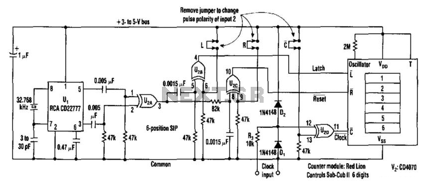
This counter facilitates the direct readout of frequency-generating equipment by incorporating a 1-Hz time base to latch, reset, and condition the count signal. The design allows for the selection of either polarity. By differentiating, inverting, and ORing the clock...
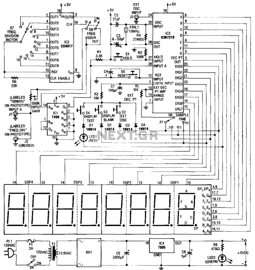
Built around an Intersil 7216 frequency counter IC, this counter has a basic range of 10 MHz, a 100-MHz prescaler, and an extra frequency divider (IC3). This divider reduces the frequency by an additional factor, as indicated on S7...
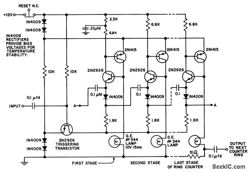
The circuit utilizes only six components per stage. By integrating counter and indicator functions, it achieves low battery consumption. Once the reset button is released, a 0.22 µF capacitor ensures that the first stage activates. Current is drawn by...
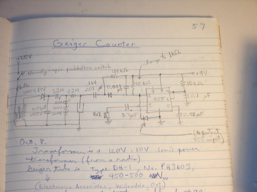
This is a simple Geiger counter circuit designed for quick publication, potentially useful for individuals in Japan. It requires some specialized components. The simple Geiger counter circuit typically consists of a Geiger-Müller (GM) tube, which is the primary sensing element...
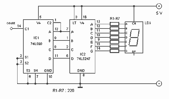
With this counter you can count laps for example (in conjunction with the Simple light trap). The circuit uses two TTL ICs 74LSxx the series. The left IC is a decimaalteller. The input pulses 14 are counted and converted...
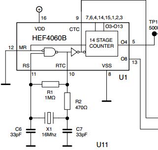
The initial issue pertains to the 16 MHz crystal oscillator, which fails to initiate oscillation. However, when substituting the 16 MHz crystal with an 11 MHz or lower frequency crystal, the oscillator functions correctly. An oscilloscope reveals a clear...