
2SC1946A 30 Watt VHF Amplifier

The 30-watt amplifier circuit is a well-engineered design suitable for FM broadcasting applications. The 2SC1946A transistor serves as the primary amplification element, chosen for its high frequency and power handling capabilities. This transistor's characteristics ensure that the amplifier remains stable under varying load conditions, which is crucial for maintaining audio fidelity in broadcasting.
The inclusion of a seven-element Butterworth low-pass filter is significant, as it effectively attenuates unwanted harmonic frequencies, ensuring that the output remains clean and compliant with broadcasting regulations. The design's attention to decoupling in the power line is critical, as it minimizes noise and interference that could affect performance.
The construction of the coils from 16-gauge laminated wire or silver copper wire contributes to the overall efficiency of the amplifier. The choice of materials and construction techniques directly impacts the amplifier's performance, particularly in high-frequency applications. The use of an HF toroid core or ferrite bead for the RF choke is a common practice in RF design, as these components help maintain signal integrity while minimizing losses.
The snubber circuit formed by C3 and R1 plays a vital role in protecting the amplifier from voltage spikes, while R2 and C6 are essential for stabilizing the circuit and preventing oscillations that could lead to signal distortion. The optional addition of a 180-ohm resistor in parallel with L7 demonstrates the design's flexibility, allowing for fine-tuning to optimize performance.
The description of the 60-watt VHF power amplifier highlights the scalability of this design. By utilizing two 2SC1946A transistors, the circuit can achieve higher power outputs, although this introduces complexity through the need for a power combiner network. This aspect emphasizes the importance of careful design consideration when scaling power levels in RF applications.
Overall, this amplifier circuit is a robust solution for FM broadcasting, with a focus on stability, efficiency, and clean output. Proper tuning and matching of the input and output networks are essential steps in the setup process, ensuring optimal performance and maximizing the amplifier's capabilities.The 30 watt amplifier schematic shown below provides an appropriate power boost with an input of 4 watt up to 6 watts. The circuit is designed to cover 88-108MHz FM Broadcast Band. However, the circuit is very stable at my place and provides a clean-output through seven (7) element Butter-worth low-pass filter.
The heart of the circuit is 2SC1946A VHF RF power transistor. The transistor is specifically designed for operation in frequencies up to 175 MHz, with very good results. As you can see, the power line is well decoupled. The amplifier current can be over 5 amps. All the coils are made from 16gauge laminated wire (or Silver copper wire can do best) and the RFC can be of HF toroid core (as shown in the picture) or 6 holes ferrite bead.
C3 and R1 forms snubber circuit while R2 and C6 prevent the amplifier from self-oscillation at VHF, sometimes you need to add 180 ohms in parallel with L7. That will cause the amplifier to dissipate UNDESIRABLE VHF thereby reducing spurious level. The photo below is 60Watts VHF power amplifier using the above circuit. Two of 2SC1946A transistors are arranged at 90 degrees to each other and their outputs are combined using "Power Combiner Network`.
It is quite difficult to combine powers at VHF and UHF bands. However, I recommend that hobbies should stick to single power design due to its complicity and large rate of INTERFERENCE. (in attempt to go for double transistors which involves power combiner network). Since the two amplifiers are operating in different phase (out of phase). Tuning of the amplifier is not hard at all. You just have to connect the output to a good antenna with a transmission line (RG214) of 50 ohms. First match the output network, and then do the same to the input network for a maximum power output.
By way of adjustment, you can increase the output at its operating frequency. 🔗 External reference
Related Circuits
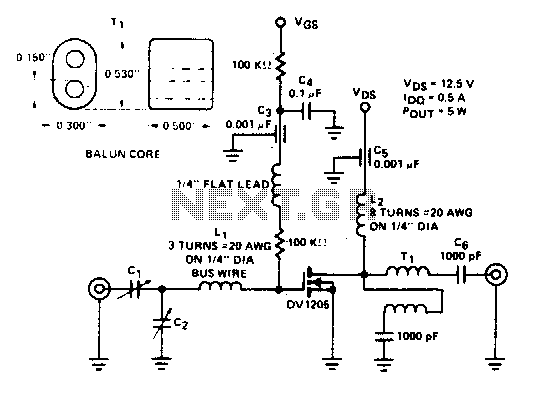
Cl. C2 ARCO #462, 2 to 60 pF, trimmer capacitors Li, 3 turns of #20 AWG wire on 1/4" diameter L2, β turns of #20 AWG on 1/4" diameter Ti. Additionally, there is 1 turn of 25 Ω coax...
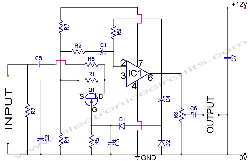
A section of the operational amplifier's output signal is rectified using 1N4148 diodes, followed by filtering, and is then directed to the gate of the FET input shunting circuit. As the output voltage increases, additional input shunting occurs, which...
This is a Class AB audio power amplifier utilizing the Hitachi HA13118 module, suitable for car applications. It can also be used in various other settings. The Class AB audio power amplifier is designed to deliver high-quality sound reproduction while...
60W Bass Amplifier. It features low-cut and bass controls. The output power is 40W on 8 Ohm loads and 60W on 4 Ohm loads. An amplifier circuit diagram is provided. The 60W bass amplifier is designed to deliver robust audio...
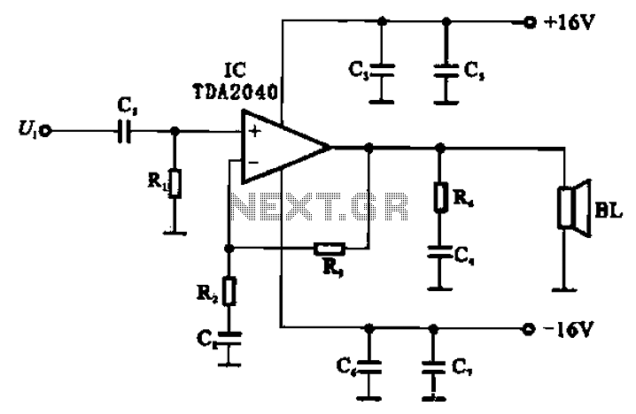
An integrated power amplifier, TDA2040 (IC), can be configured as an OCL (Output Capacitor-Less) power amplifier. The circuit, illustrated in Figure 10-10, operates using a symmetrical ±1V dual supply voltage. The OCL amplifier benefits from the positive and negative...
Connect two 24 V / 3 W bulbs in parallel to the output and set the right frequency on PLL. Now turn on the transmitter. You should tune it on a receiver. Maybe you might stretch coils of the...