Simple Combination Lock
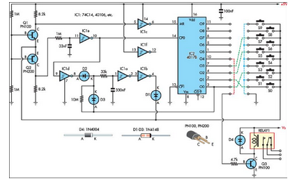
This simple combination lock accommodates codes ranging from 1 to 9 digits in length, with the only restriction being that the same digit cannot be used twice. The circuit...
A combination lock circuit can be designed using a microcontroller or a series of logic gates that facilitate the entry and validation of a numerical code. The core functionality involves a keypad input for code entry, a microcontroller for processing the input, and an output mechanism, such as an LED or a buzzer, to indicate whether the entered code is correct or incorrect.
The circuit typically includes a numeric keypad consisting of buttons labeled with digits 0-9. Each button press is detected by the microcontroller, which records the sequence of inputs. The microcontroller is programmed with an array that holds the valid combination codes. It is essential to ensure that the code entry does not repeat any digit, which can be managed through software logic that checks for previously entered digits before allowing a new entry.
Power supply considerations must also be addressed, with the circuit requiring a stable voltage source, typically between 3V to 5V, depending on the microcontroller specifications. Additionally, debouncing techniques may be necessary to ensure that multiple signals are not registered from a single button press due to mechanical bounce.
The output stage can include visual indicators such as LEDs to signal success or failure of code entry. For enhanced security, the circuit can also incorporate a time delay after a certain number of incorrect attempts, locking the system temporarily to prevent brute-force attacks.
Overall, the design of this combination lock circuit emphasizes user input validation, security, and feedback mechanisms to create a reliable and effective locking system.This simple combination lock accommodates codes from 1-9 digits long, with the only restriction being that the same digit cannot be used twice. The circui.. 🔗 External reference
Warning: include(partials/cookie-banner.php): Failed to open stream: Permission denied in /var/www/html/nextgr/view-circuit.php on line 713
Warning: include(): Failed opening 'partials/cookie-banner.php' for inclusion (include_path='.:/usr/share/php') in /var/www/html/nextgr/view-circuit.php on line 713
