
Simple circuit diagram repellent

The described circuit operates by generating high-frequency sound waves that are unpleasant to rodents and other small animals, effectively acting as a deterrent. The core component, the CMOS 4047 integrated circuit, is configured as a relaxation oscillator. This configuration enables the circuit to produce a square wave output, the frequency of which can be fine-tuned using the adjustable potentiometer P1. The output frequency range of 5 kHz to 30 kHz is particularly effective, as many pests are sensitive to ultrasonic frequencies.
The non-inverting amplifiers (IC2 and IC3) serve to boost the output signal from the 4047 circuit, ensuring that sufficient power is delivered to the subsequent transistor stages. The parallel connection of the six stages enhances the overall output power, allowing for more robust operation of the connected transistors. Transistors T1 and T2, as well as T3 and T4, work in pairs to drive the piezoelectric speaker, which converts the electrical signals into sound waves.
The circuit operates with a power supply providing 15-18 VDC, which is adequate for the functioning of the amplifiers and transistors. The piezoelectric speaker is chosen for its ability to produce high-frequency sounds efficiently, contributing to the effectiveness of the repellent circuit. This design is particularly advantageous for its simplicity and cost-effectiveness, making it accessible for widespread use in pest control applications.A very cheap and simple repellents can be used for rats, mice and other animals may use electronic figure below. Circuit using CMOS integrated circuit type 4047 is connected to function as a relaxation oscillator whose frequency can be adjusted between 5 kHz to 30 kHz, the potentiometer P1. Q and Q outputs of each section are applicable to each of the non-inverting amplifier 4050 type, IC2 and IC3.
Each of the six stages of the integrated circuit, connected in parallel, allowing direct attack transistors T1/T2, respectively T3/T4 T1 or T2 and T4 and T3 simultaneously. These pairs of transistors can attack the piezoelectric speaker. Circuit provides a 15-18 Vdc
Related Circuits
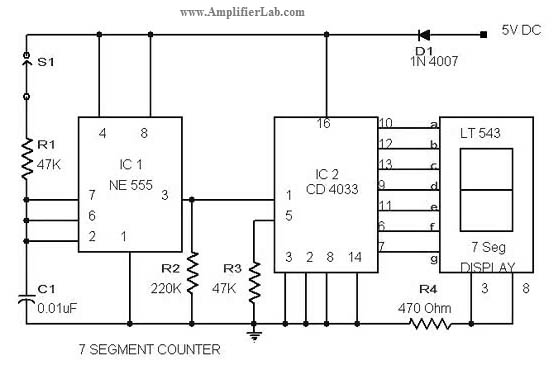
The circuit diagram of a 7-segment counter circuit has been published here. This circuit consists of the counter IC CD4033 as its central component. The 7-segment counter circuit utilizing the CD4033 integrated circuit (IC) is designed to display decimal digits...
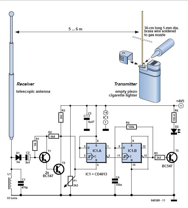
In 1896, Marconi successfully transmitted electromagnetic waves over a distance of approximately 3 kilometers. Shortly thereafter, he established radio communication across water between Lavernock Point in South Wales and Flat Holm Island. The transmitter utilized a spark inductor connected...
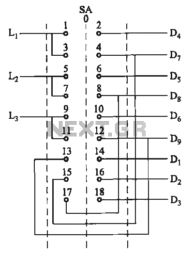
The motor switch control circuit depicted in the figure provides two speed settings for counter-steering, allowing for operation at two speeds in opposite directions. The motor switch control circuit is designed to facilitate the operation of a motor at two...
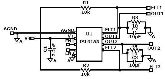
The ISL6185 USB power controller family can be utilized to design a straightforward USB power supply electronic project that offers fully independent overcurrent (OC) fault protection for two or more USB ports. This product family includes sixteen distinct functional...
Wind 6 turns of solid wire on a pen or pencil that is just under 1/2 inch in diameter. Remove the wire from the pencil and spread the winding to make a length of 3/4 inch. Solder C2 somewhere...
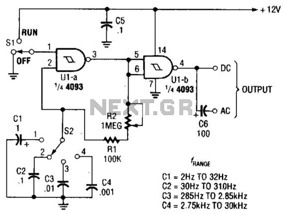
The circuit illustrated operates within a frequency range of 2 Hz to 30 kHz. Additionally, R2 is configured as either a linear or logarithmic potentiometer. The circuit is designed to accommodate a wide frequency spectrum, making it suitable for various...