
3 Band Audio Equalizer Circuit

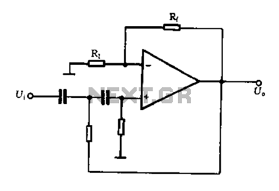
The three-band equalizer circuit employs an active filter configuration, which provides enhanced control over audio frequency response compared to passive filters. The circuit consists of three separate filter stages, each dedicated to a specific frequency range: low frequencies (bass), mid frequencies, and high frequencies. The LM833 op-amp is chosen for its low noise characteristics and high performance, making it suitable for audio applications.
Each band is controlled by a potentiometer, allowing the user to adjust the gain applied to that specific frequency range. The feedback network of each op-amp stage is designed to set the gain and frequency response characteristics. The 100K potentiometers used in the feedback paths introduce slight DC variations, which can affect the overall performance of the circuit. To mitigate any potential issues related to DC offset at the output, a coupling capacitor may be implemented, ensuring that only the AC audio signal is passed to subsequent stages or to the output.
The circuit's maximum equalization capability of 15 dB provides significant flexibility for tailoring audio output to suit different listening environments or personal preferences. The noise attenuation of 90 dB at the middle position of the potentiometer indicates that the circuit is highly effective at minimizing unwanted noise, which is crucial in high-fidelity audio applications. The bandwidth of 1 MHz ensures that the equalizer can handle a wide range of audio frequencies without significant roll-off, maintaining audio quality across the spectrum.
The gain adjustment formula, Vu = R2/R1, allows for precise control over the gain of the circuit, enabling users to customize the equalization effect further. By selecting appropriate resistor values for R1 and R2, the gain can be adjusted to meet specific audio requirements, enhancing the overall versatility of the equalizer circuit. This design is suitable for various applications, including home audio systems, professional sound reinforcement, and musical instrument amplification.This 3 band equalizer circuit is an active filter network for bass, mid and high audio ranges. It is designed around the LM833 opamp from National Semiconductors. The output of this 3 way graphic equalizer is designed to be DC coupled, however due to slight DC variations through the 100K potentiometers at the feedback lines of the opamp A2, a coup ling capacitor might be needed. The maximum equalizer range is about 15 dB. In the middle position of potentiometer, the noise attenuation is about 90 dB with a bandwidth of 1 MHz and a gain of 0 dB. The gain can be changed through R2 using the following formula: Vu = R2/R1. 🔗 External reference
Related Circuits
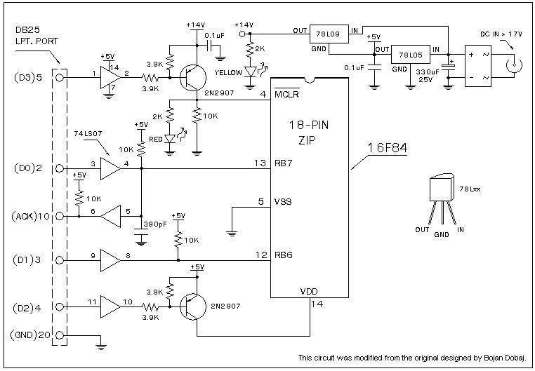
A universal Windows-based software designed to work with any serial programmers for the PIC16F84, known as WPicProg16 V1.20. It is recommended to build this programmer before starting various interesting projects with the F84. Some PIC programmers support in-circuit programming,...
A typical two high-pass filter circuit. A high-pass filter (HPF) is an electronic circuit that allows signals with a frequency higher than a certain cutoff frequency to pass through while attenuating signals with frequencies lower than the cutoff frequency. A...
The water tank overflow liquid level sensor alarm circuit is a straightforward electronics project suitable for school students. Previous discussions have covered numeric water level indicators and water level controller circuits, which are more complex and intended for engineering...
The circuit was designed to create a line preamplifier using double triode tubes. It consists of three parts, including the main preamplifier. The line preamplifier circuit utilizing double triode tubes is structured to enhance audio signals by amplifying low-level signals...
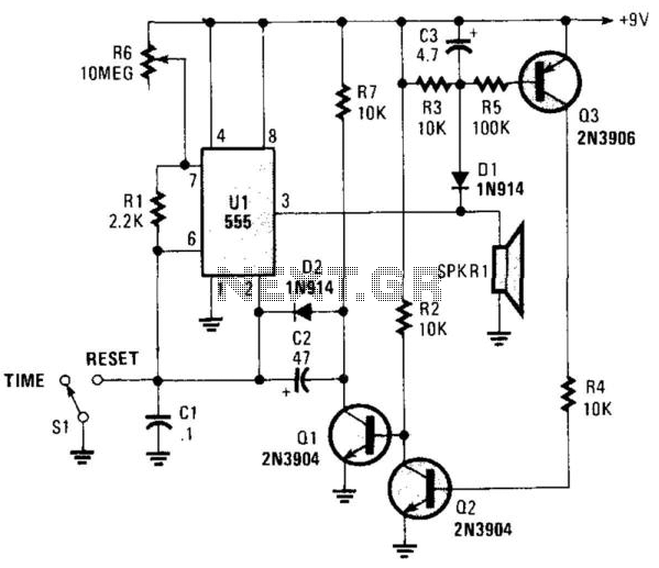
This circuit operates in astable mode and produces a tone at the end of the first period, which can last several minutes. When switch SI is in the time position, transistor Q3 is turned off because pin 3 of...
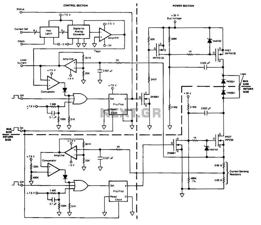
This circuit facilitates on/off switching, soft starting, current monitoring, current tripping, and overcurrent protection for a 30 Vdc power supply, accommodating normal load currents of up to 2 A. The switch is activated by an "on" command pulse and...