
Wideband FM Jammer

The wideband jammer circuit operates by utilizing a combination of key components including a modulator, varactor diodes, operational amplifiers, and a power supply. The modulator serves as the core element where the sawtooth signal is generated and modulated to create the jamming effect. Varactor diodes are crucial for tuning, as their capacitance varies with the applied voltage, allowing for dynamic frequency modulation across the desired band.
The sawtooth signal generator is designed to produce a linear ramp voltage that continuously sweeps through the frequency range. This is achieved through a capacitor charging and discharging mechanism, which creates the sawtooth waveform. The frequency of the generated signal can be finely tuned by adjusting the values of the varactor diodes in conjunction with the sawtooth signal.
Operational amplifiers are employed to amplify and filter the jamming signal, ensuring that it maintains a consistent output power level. The design includes provisions for separate power supply connections to enhance stability and reduce noise, which could otherwise interfere with the jamming signal's clarity.
The output stage of the transmitter connects to either a dummy load or a discone antenna, with impedance matching facilitated by trimmer capacitors. These capacitors are critical for minimizing signal reflection and maximizing power transfer, which is essential for effective jamming performance. The SWR meter is employed to monitor the efficiency of the antenna system, guiding the user in achieving optimal performance.
In terms of safety and legality, it is imperative to adhere to local regulations regarding radio frequency transmission. The circuit should be constructed with appropriate RF shielding to prevent unintended emissions and to protect sensitive components from interference. The power supply design incorporates protective features to prevent over-voltage conditions that could damage the circuit components, particularly the transistors.
Overall, this wideband jammer circuit represents a sophisticated approach to RF jamming, leveraging a combination of electronic principles and components to achieve its intended functionality while emphasizing the importance of responsible use and compliance with legal standards.This wideband jammer simultaneously blocks all transmissions within a desired band typically by sweeping across the desired band to be blocked, starting at the lowest frequency and ending at the highest frequency of the band. For this purpose a linear sawtooth signal is applied to the modulator in the FM transmitter described here.
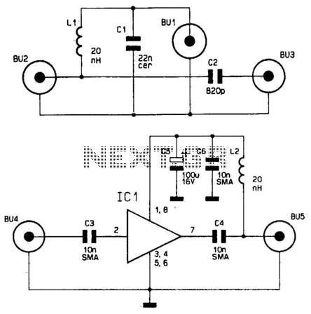
The transmit ter uses varactor diodes in the tuning circuit to determine the transmitters frequency of operation. Applying a sawtooth signal to the varactor diodes results in the transmission frequency changing with respect to the changing voltage of the sawtooth. As the voltage of the sawtooth signal increases so does the frequency at which the transmitter transmits.
This cycle is repeated many times a second. A sawtooth signal generator is shown in Below figure. To ensure the jamming signal sounds natural, white noise is added to the sawtooth signal. To improve stability, consider feeding power to the Operational Amplifiers seperately be means of a voltage divider for each (use the same component values as shown in the schematic). For experimentation purposes and to prevent unwanted interference, connect the output of the transmitter to a 50 Ohm/10 W resistor dummy load.
In practice the transmitter would be connected to a wideband VHF antenna (but that may be illegal). To match the impedance between the transmitter and antenna/ dummy load adjust the two trimmer capacitors in the last stage until the best match is obtained.
To measure the SWR use a SWR meter. A SWR of 1:1. 5 or better can easily be achieved when connecting the transmitter to a 30 MHz to 800 MHz discone antenna (a wideband antenna such as a discone or similar is recommended for best results). The adjustment of the trimmer capacitors is not described here, trial-and-error was used. Start with the first and end with the last making small adjustments each time until the desired effect is achieved (be patient, it will eventually work correctly).
It is important to note that the trimmer capacitor connected to the emitter and collector of transistor TR1 is adjusted such that the modulator oscillates correctly as it is the source of the jamming signal. Using a FM radio, listen to the transmitted signal, you should only hear white-noise when the trimmer capacitors are correctly adjusted.
With the trimmer capacitors adjusted correctly the transmitter output power is approximately +30 dB to +40 dB across the band, which is theoretically sufficient to block all stations within a radius of about twenty to fifty metres from the antenna. A transmitter with lower output power is shown in figure b(2). Standard RF shielding techniques should be used, i. e. RF shielding between transmitter, power supply, sawtooth and white-noise signal generator, connecting ground of all circuits to chassis, etc.
The power supply, shown in figure c, consists of two 30 Volt adjustable power supplies. The first, feeding power to the FM transmitter, should be adjusted to a maximum voltage of 17 Volts because the maximum Vce voltage of transistor TR4 is 17 Volts. Applying voltages above this will result in permanently damaging the transistor. FM transmitters are susceptible to mains hum, therefore a ripple filter (consisting of a large capacitor and choke) is included in power supply feeding the transmitter.
Disclaimer: Build and/or use this device strictly at your own discretion as it is illegal to operate a radio frequency jammer in most countries. The design is intended for controlled experimentation and to describe the principle of RF jamming only.
The owner of this web site does not endorse any unlawful use of this device. You are strongly encouraged to observe the regulations of your countries national telecommunications authority. 🔗 External reference
Related Circuits
A GPS receiver costing less than a few hundred dollars can provide immediate location information, including latitude, longitude, and altitude, accurate to within a few hundred feet. The output from the Voltage-Controlled Oscillator (VCO) is directly connected to a...
This wideband antenna preamplifier has a gain of approximately 20 dB from 40 to 860 MHz, covering the entire VHF, FM, commercial, and UHF bands. A phantom power supply delivers DC power to the preamplifier through the coaxial cable...
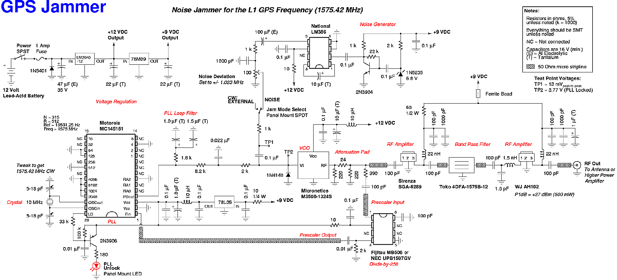
A low cost device to temporarily disable the reception of the civilian coarse acquisition (C/A) code used for the standard positioning service (SPS) on the Global Positioning System (GPS/NAVSTAR) L1 frequency of 1575.42 MHz. This is accomplished by transmitting...

This design outlines a simple wideband output amplifier suitable for use as a 50-ohm transmission line driver. The circuit is constructed using the CA3140 operational amplifier. When utilized alongside the function generator and sine wave shaper circuits, it delivers...
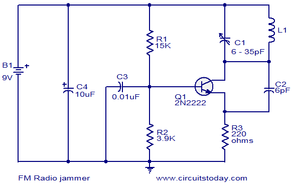
The circuit presented here can be used to jam FM radios in its vicinity. It consists of a classic single transistor oscillator operating in the VHF region. The working principle of the circuit is straightforward: powerful VHF oscillations from...
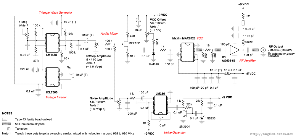
Emits a carrier that sweeps the 925-960 MHz cellular tower transmitter band (handset receive band). The described system functions as a signal generator, specifically designed to emit a carrier wave that sweeps across the frequency range of 925 to 960...