3 channel audio mixer
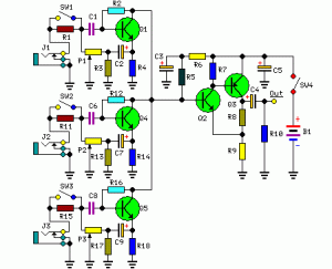
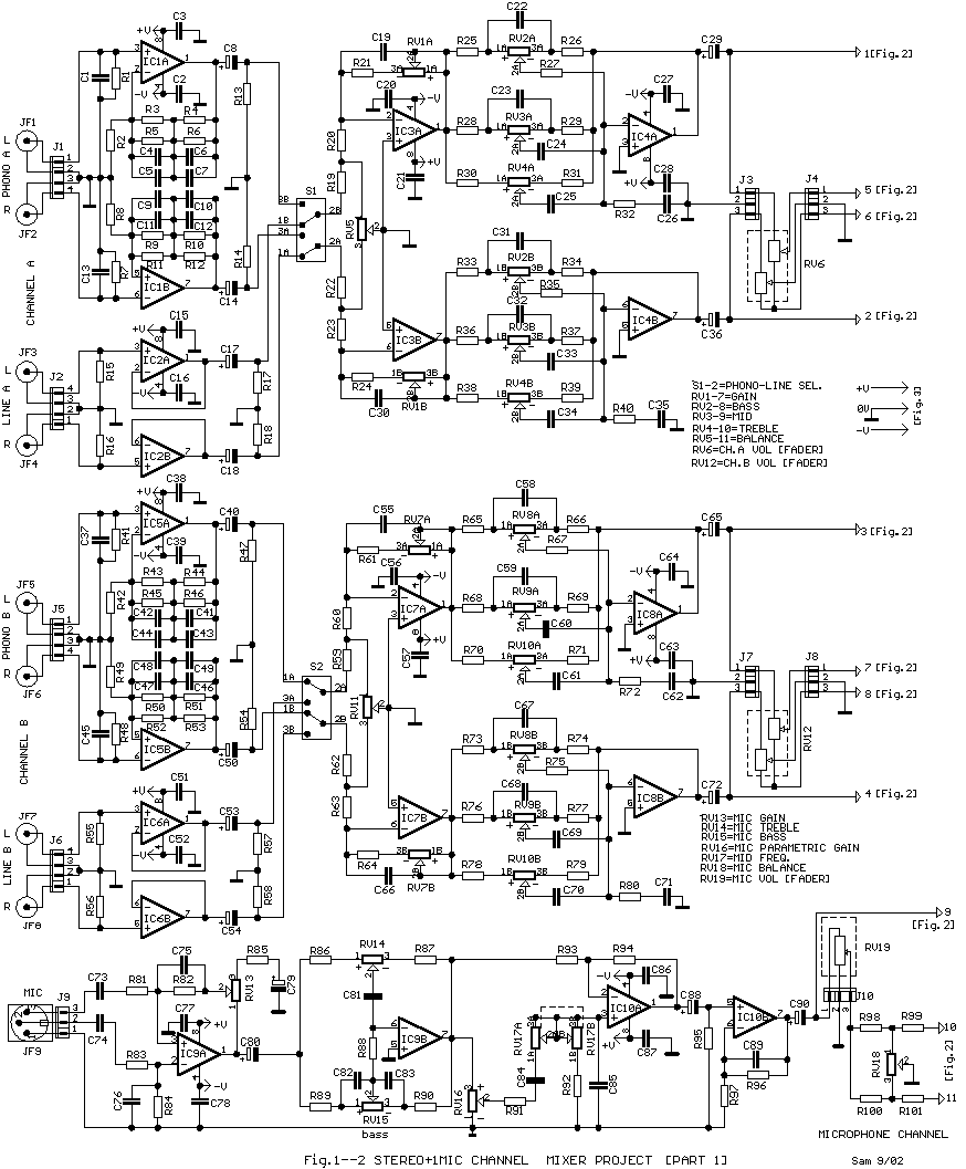
A 3-channel audio mixer circuit operates on a 9V DC voltage, which can be supplied by a battery. This mixer is specifically designed for use in public amplification applications. The audio circuit of this mixer is tailored for portable audio mixing, featuring only a volume control and lacking tone control. The provided image depicts a mono series of the audio mixer. To create a 3-channel stereo audio mixer, it is necessary to construct two units of the 3-channel audio mixer. Additional details can be found in the accompanying image of the 3-channel audio mixer.
The 3-channel audio mixer circuit is a fundamental component in audio processing, particularly in public address systems where portability and simplicity are essential. The circuit operates on a 9V DC power supply, which can be conveniently sourced from a battery, making it ideal for mobile applications.
This mixer is designed to handle three separate audio channels, allowing for the mixing of multiple audio sources. Each channel typically includes an input stage where audio signals from microphones or other sources can be connected. The absence of tone control simplifies the design, focusing on volume adjustments to maintain clarity and ease of use in public settings.
The circuit may consist of operational amplifiers configured as summing amplifiers, which mix the audio signals from the three channels into a single output. The output can then be sent to an amplifier or directly to speakers, depending on the application.
For stereo applications, two of these mono 3-channel mixers can be used in tandem, effectively creating a stereo mixer that can handle six audio channels. This setup allows for a wider sound stage and improved audio quality, which is particularly beneficial in larger venues or outdoor settings.
Careful attention should be given to the layout of the circuit board to minimize noise and interference, ensuring that the audio quality remains high. Additionally, the use of high-quality components can enhance the performance and reliability of the mixer, making it suitable for various public amplification needs.3 channel audio mixer circuit uses voltage 9VDC summber which can supplied from a battery. 3 channel audio mixer circuit is designed special for the purposes of this Public Amplifier. Because the audio circuit of this mixer is designed specifically for the purpose of a portable mixer for audio public then this series has only a volume control with out the tone control. Image series that looks below audio mixer is a series of mono, if you want to make a 3 channel stereo audio mixer it is necessary to make 2 pieces of a series of three channel audio mixer terebut. For more details, a series of three channel audio mixer can be seen in the following image. 🔗 External reference
