
differential to ttl convertor

The described system utilizes differential signaling to enhance transmission quality over various cable types, ensuring minimal signal degradation over long distances. The balanced differential outputs are crucial for maintaining signal integrity, particularly in environments susceptible to electromagnetic interference (EMI). By employing differential transmission, the circuit effectively cancels out noise that may be induced along the transmission line, thus preserving the clarity of the transmitted signal.
In practical applications, when the signal voltage diminishes below acceptable levels at the receiving end, a signal amplification circuit can be implemented. This circuit typically comprises an operational amplifier (op-amp) configured in a non-inverting or inverting mode, depending on the desired gain characteristics. The op-amp should be selected based on its bandwidth and slew rate to ensure it can handle the frequency of the input signal without distortion.
Additionally, feedback resistors can be utilized to set the gain of the amplifier, allowing for precise control over the output signal levels. It is advisable to keep the impedance matching in mind, especially when interfacing with 50-ohm to 500-ohm transmission lines, to prevent reflections that could further degrade the signal quality.
Power supply considerations for the op-amp circuit are also essential; a dual power supply may be used to accommodate the positive and negative voltage swings of the differential signal. Proper decoupling capacitors should be included to filter out any noise from the power supply lines, ensuring stable operation of the amplifier.
Overall, the integration of a boosting circuit at the receiving end enhances the reliability of differential transmission, making it suitable for applications in telecommunications, data communication, and other fields where signal integrity is paramount.The differential outputs are balanced and are designed to drive long lengths of coaxial cable, strip line, or twisted pair transmission lines with characteristic impedances of 50 ohms to 500 ohms. Differential transmission is superior to single wire transmission in that it nullifies the effects of ground shifts and noise signals which appear as co
mmon mode voltages on the transmission line. If the signal voltage at the end of the line is found to be of insufficient magnitude then the following circuit may be used (at the recipient equipment end) to boost the levels. 🔗 External reference
Related Circuits

The third Eagle layout of the program counter has been completed, presenting a clearer design compared to the previous iterations, which were cluttered with intersecting wires, making it difficult to discern connections. This diagram is intended to facilitate understanding...
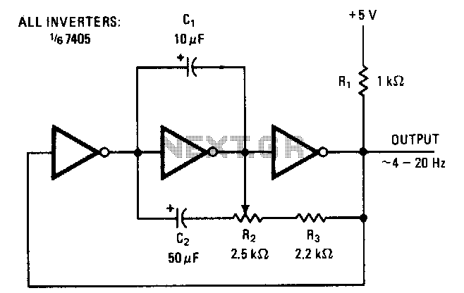
The symmetry of the square-wave output is maintained by connecting the right side of resistor R2 through resistor R3 to the output of the third amplifier stage. This configuration alters the charging current to the capacitors in proportion to...
In the circuit shown below, if the voltage at the output terminals rises above 6.2V, zener conducts charging capacitor C4. This voltage will fire the silicon-controlled rectifier (SCR), which quickly shorts across the supply rails blowing the fuse. The...
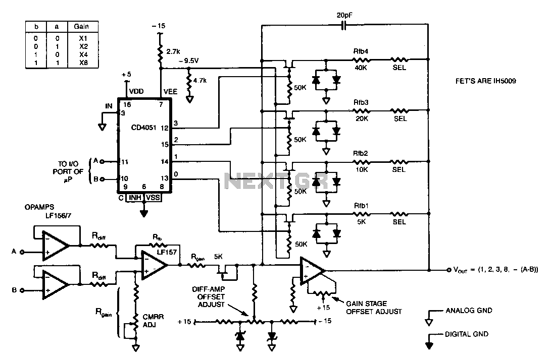
This programmable gain circuit utilizes a CD4051 CMOS Analog Multiplexer as a two to four line decoder, featuring appropriate FET drive for switching between feedback resistors to set the gain to one of four selectable values. The described programmable gain...
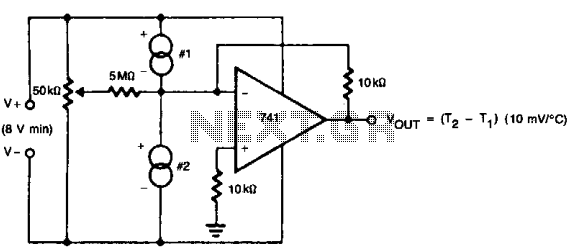
The 50 k ohm potentiometer adjusts offsets in devices, whether internal or external, allowing for the setting of the difference interval size. This feature makes it suitable for liquid-level detection, particularly in scenarios where a measurable temperature difference exists. The...

This circuit will generate a smaller DC output voltage from a larger DC input voltage. It is quick and simple to make and by changing the value of the zener diode, the circuit can be universally adapted to provide...