
3 in one doorbell

The power supply circuit is essential for ensuring stable voltage levels for the operation of the microcontroller and other components. The transformer TR1 is responsible for stepping down the AC voltage from the mains supply to a lower level suitable for rectification. Q3 and Q1 are typically configured as voltage regulators or switching devices that help maintain the desired output voltage levels.
D13 and D9 are diodes that serve multiple purposes, including rectification and protection against reverse polarity. The diodes convert the AC voltage from the transformer into a pulsating DC voltage, which is then smoothed by capacitors (not mentioned in the original input but commonly included in such circuits) to provide a stable DC output.
The 12-volt rail is often utilized for powering larger components or devices requiring higher voltage, while the 5-volt rail is primarily used to power the microcontroller and its peripheral components. Proper decoupling capacitors should be placed close to the microcontroller's power pins to filter out any noise and provide instantaneous current during transient conditions.
In summary, the described circuit is a fundamental power supply design that ensures reliable operation of microcontroller-based systems by providing necessary voltage levels and protecting against potential electrical faults.The circuit comprises the power supply which is formed by TR1, Q3, D13, Q1, D9 This supplies both the 12 volt rails and the five volt rails for the micro which i.. 🔗 External reference
Related Circuits

The ping of the cymbals, crack of the snare drum, thonk of the bass - none of these comes through on my low-budget speakers. Sometimes they sound so fuzzy I want to hide behind the couch until it’s over....
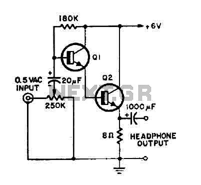
This is a simple headphone amplifier. Any NPN transistor can be used. The circuit can be powered by a 9V battery. The headphone amplifier circuit serves to boost audio signals to a level suitable for driving headphones. It typically consists...

The 2N2222 circuitry is a three-element phase-shift oscillator circuit designed to produce a 1,000 Hz sine wave. This sine wave is subsequently applied to the TCG-610 varactor diode, which has a capacitance of 6 pF at 4 V. The...
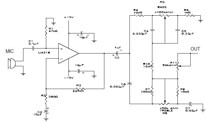
This electronic project is a simple microphone preamplifier based on the LM318 operational amplifier. The LM318 is configured as a standard non-inverting amplifier. Resistor R1 provides a ground reference for the bias current of the non-inverting input. The combination...

Alarm system designs often require circuitry that can detect whether a phone line is active or broken. The primary challenge in this design is to draw less than 5 µA from the phone line, which operates within a voltage...
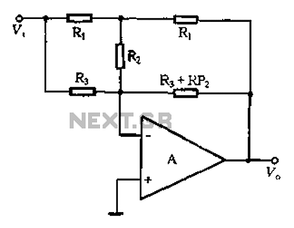
At high frequencies, the capacitor Cz can be considered a short circuit (i.e., the resistance of the RPi is negligible). This is illustrated in Figure 4-6 (a) of the apparatus, which corresponds to the equivalent circuit shown in Figure...