
30 LED audio frequency analyzer

The circuit described functions as an acoustic signal analyzer, utilizing light-emitting diodes (LEDs) to visually represent the characteristics of the input signal. The key components include the LM3915 (IC1), a voltage level indicator that drives the LEDs based on the input signal's amplitude and frequency. The circuit is designed to respond to varying frequencies and amplitudes of acoustic signals, where the brightness of the LEDs indicates the amplitude of the signal and the color indicates the frequency range.
The resistors R1, R2, and R3 configure the circuit's sensitivity and response characteristics. R2, being a variable resistor (trimmer), allows for fine-tuning of the input sensitivity, enabling the circuit to adapt to different signal strengths. The values of R4 and R5 can also be adjusted to optimize the response of the system, allowing for a customized experience based on the specific application.
The use of three distinct LED colors — red, yellow, and green — provides a clear visual indication of the signal's characteristics. The red LED indicates high amplitude signals, the yellow LED indicates medium amplitude signals, and the green LED indicates low amplitude signals. This color-coded system enables users to quickly assess the nature of the incoming acoustic signal.
The counter decoder (IC2, 4017) plays a crucial role in managing the output to the LEDs, ensuring that the correct LED lights up based on the input conditions. The additional gates (IC3, 4011) may be used to further manipulate the signal or to create additional logic functions as required by the application.
Capacitance is provided by C1 (100nF, 100V), which can help filter the input signal, smoothing out any rapid fluctuations and ensuring that the circuit responds accurately to the average signal levels. The design does not focus on precision measurements but rather on providing a visual representation of the signal's characteristics.
Overall, this circuit serves as an effective tool for analyzing acoustic signals, with its adjustable components allowing for flexibility in various applications, from educational experiments to more advanced signal processing tasks. This analyst is, a sensitive instrument, in the frequency changes and width of a acoustic signal. Thus the brightness of LED that turns on each moment of is proportional signal width, while the colour of proportionally frequency. The circuit input sensitivity is regulated with R2, in order that in powerful signals they turn on the red LED, in the middle the yellow LED and in the low green LED.
The display unit, is constituted by 3 lines of 10 LED the every, what is checked by a counter decoder (IC2). Two gates IC?-b, function as the IC2, with the R6 regulate the frequency. When does not exist signal in the input, then no one LED does not turn on. As soon as it will be applied signal, then the LED will begin to blink depending on the rythm and the intensity of signal.
Can experiment with the prices of resistances R4, R5, so that you find the value that suits in like your. Initially it can they are placed trimmer 1K?, in the place of R4, R5 and after is found the suitable value, they are replaced with permanent resistances.
What it wants it can it adds also other LED, adding other a completed same press with the IC2. The particular circuit does not have the claim, the precision of measurement input signal. Part List R1= 1K8Kohm R6= 100Kohm trimmer IC1= LM3915 R2= 100Kohm trimmer C1= 100nF 100V IC2= 4017 R3= 1Kohm D1....10= RED LED IC3= 4011 R4= 100 ohm.....1Kohm D11....20= YELLOW LED R5= 100 ohm.....1Kohm D21....30= GREEN LED 🔗 External reference
Related Circuits
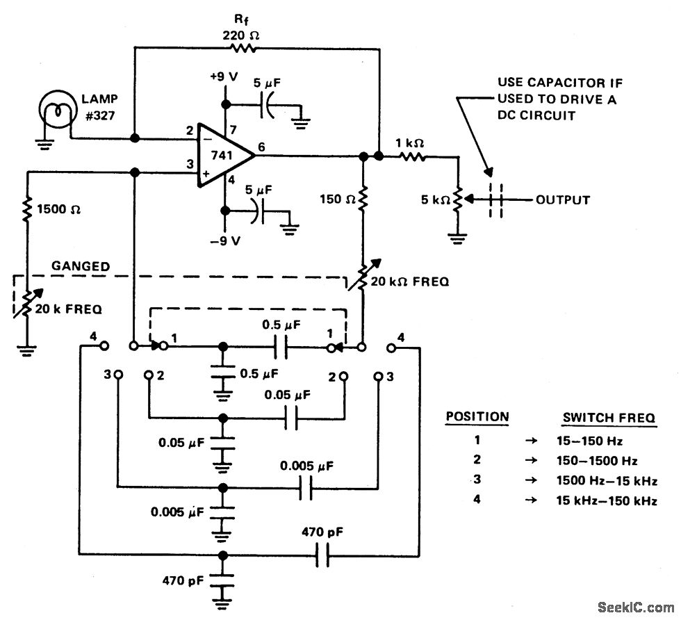
A Wien bridge oscillator generates sine waves with minimal distortion. It produces zero phase shift at a specific frequency (f=1/2 RC), which is the frequency of oscillation. Stable oscillation is achieved when the loop gain is maintained at unity...
Can be directly connected to CD players, tuners and tape recorders. Simply add a 10K Log potentiometer (dual gang for stereo) and a switch to cope with the various sources you need. A correct grounding is very important to...
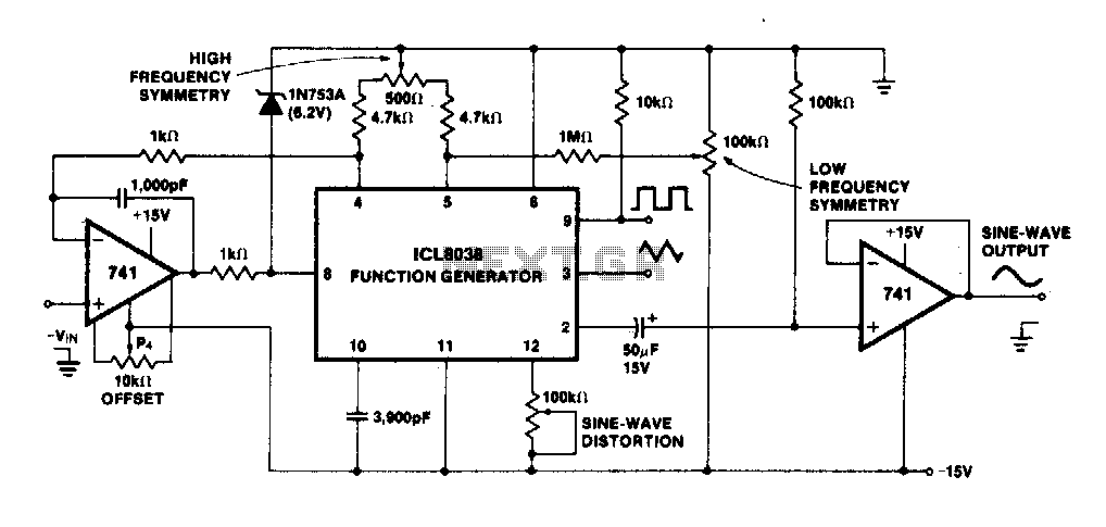
The linearity of the input sweep voltage in relation to the output frequency is significantly enhanced by utilizing an operational amplifier. The utilization of an operational amplifier (op-amp) in electronic circuits is a common practice to improve the linearity of...
This page features a replacement circuit for the LM3909 LED Flasher / Oscillator using discrete components. The circuit is functionally the same as the integrated LM3909 but has a minor variation of the components used. Naturally the circuit will...
This application note outlines the development and implementation of a Digital Weigh-Scale (DWS) utilizing Zilog's Z8 Encore! Microcontroller. The reference design provides a ready-to-use DWS solution that is easily scalable for measuring high-capacity loads. An external high-resolution Analog-to-Digital Converter...
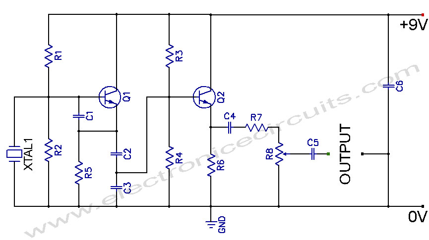
Crystal Controlled Oscillator Circuit. This general-purpose signal source is highly effective in signal-tracing applications. The output level is adjustable. The crystal-controlled oscillator circuit is designed to provide a stable and precise frequency output, which is essential for various electronic applications,...