
300mW FM Transmitter

The TX300 FM transmitter circuit is designed to provide a simplified solution for FM transmission, particularly suitable for personal use in small areas such as homes and yards. The circuit architecture mirrors that of the TX500, with the notable modification of employing a single-stage variable VHF amplifier, which streamlines the design and reduces component count.
The transmitter operates by utilizing a VHF amplifier (Q2) and an oscillator (Q1). The gain control potentiometer (P1) allows users to adjust the output power and transmission distance, providing flexibility based on the user's needs. This feature is particularly advantageous for those who wish to modulate their audio signals with varying ranges, accommodating different environments and requirements.
In cases where enhanced transmission power is desired, the circuit allows for the substitution of Q2 with higher-power transistors such as the 2N4427 or 2N3866. However, this modification necessitates the replacement of P1 with a fixed resistor to manage the increased current demands of the more powerful transistor.
The circuit is designed on a separate board, facilitating integration with a smaller printed circuit board (PCB) for compact assembly. This modular approach enhances usability and allows for easier adjustments and testing. Additionally, a power meter is incorporated into the design to measure the output power from both the VHF amplifier (Q2) and the oscillator (Q1), providing essential feedback for tuning and optimization.
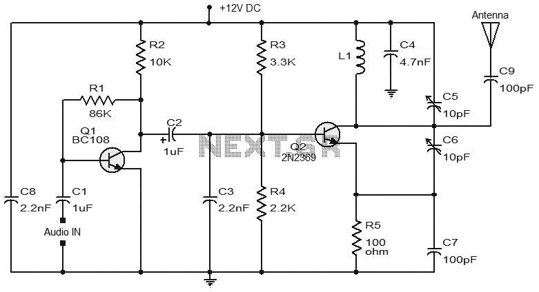
The coils used in the TX300 are identical to those in the TX500, ensuring compatibility and performance consistency across both models. This design choice further simplifies the construction process, as users can leverage existing components from the TX500 for their TX300 builds. Overall, the TX300 FM transmitter represents an efficient and user-friendly option for personal FM broadcasting.Here it is a brand new TX300 FM transmitter. The amplifier has exactly the same architecture as TX500 with the difference that TX300 has only one stage variable VHF amplifier. It is a cute schematic that was made for all of you who wanted something even simpler than TX500 and with not as many necessary parts.
It is a perfect circuit for transmitting your music around the house and yard. Interesting feature is a gain control P1 that lets you adjust your desired output power and distance. If in case you want to replace Q2 with more powerful transmitter like 2n4427 or 2n3866 you will have to replace P1 with a resistor due to the higher necessary current.
For much more info go to TX500`s page. This power meter will let you test both the output power of Q2 (VHF amp) and Q1 (oscillator). Circuit is now on the separate board so you can fit the main circuit of the smaller PC board. Coils: TX300 uses exactly the same coils as TX500 w 🔗 External reference
Related Circuits
In this project, you will make a simple 3-stage low-power broadcast-type circuit, using a crystal oscillator integrated circuit and a collector modulated AM oscillator with amplifier. You can connect the circuit to an electret microphone or amplified dynamic microphone....
Numerous FM transmitter circuits have been published, and this is another example of a simple two-transistor FM transmitter. The first stage of the circuit is a preamplifier based on transistor Q1. This stage operates as a collector-to-base biased amplifier,...
An FM modulator that modulates a carrier frequency with the composite signal, and an RF amplifier that provides enough power to be transmitted through an antenna. Here is the schematic diagram of the FM transmitter circuit: The core of...
The transmitter utilizes a 6BW6 vacuum tube to achieve an output power of approximately 5 watts. The circuit includes a component CI that is calibrated to produce the cleanest continuous wave (CW) note. The tuning capacitors C8 and C9...
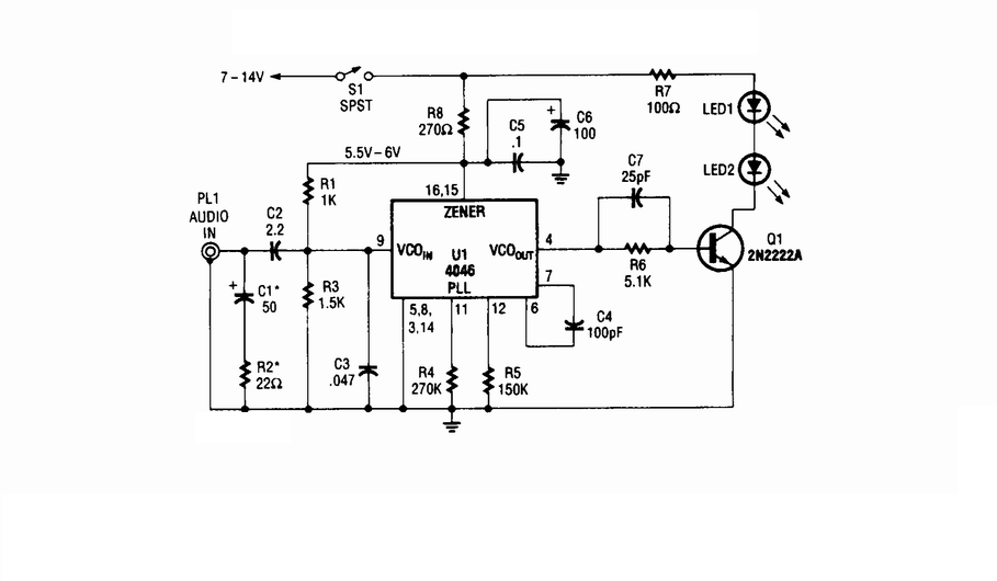
Wireless infrared headphone transmitter. Audio input from PL1 frequency modulates the voltage-controlled oscillator (VCO) section of a 4046 phase-locked loop (PLL) chip. The VCO output drives Q1, a switching transistor, which in turn drives two infrared (IR) LEDs. The wireless...
This FM transmitter circuit employs four radio frequency stages: a VHF oscillator built around the transistor BF494 (T1), a preamplifier constructed with the transistor BF200 (T2), a driver using the transistor 2N2219 (T3), and a power amplifier based on...