
1watt AM/CW 10-meter band transmitter

The described circuit is a low-power AM transmitter that operates in three stages, incorporating a crystal oscillator, a modulator, and an amplifier. The use of a crystal oscillator integrated circuit ensures stable frequency generation, which is crucial for maintaining clear signal transmission over the AM band.
The first stage consists of the crystal oscillator, which generates a carrier frequency. This frequency is determined by the crystal's specifications and is typically in the range of 530 kHz to 1700 kHz, which is the AM broadcast band. The output of this oscillator is then fed into the second stage, which is a collector modulated AM oscillator. This stage modulates the carrier signal with audio input from a microphone.
An electret microphone is preferred for this application due to its sufficient output voltage (at least 100 mV), which is necessary for effective modulation. If a dynamic microphone is used, a low-frequency preamplifier stage, typically utilizing a single transistor, can be added to boost the microphone's output to the required level. This preamp stage enhances the signal before it reaches the modulator, ensuring that the audio is adequately represented in the transmitted signal.
The final stage of the circuit is an amplifier that increases the power of the modulated signal. This stage is crucial for broadcasting the signal over a distance, allowing it to be picked up by standard AM radio receivers. The amplifier should be designed to match the characteristics of the modulated signal while providing sufficient power to ensure effective transmission.
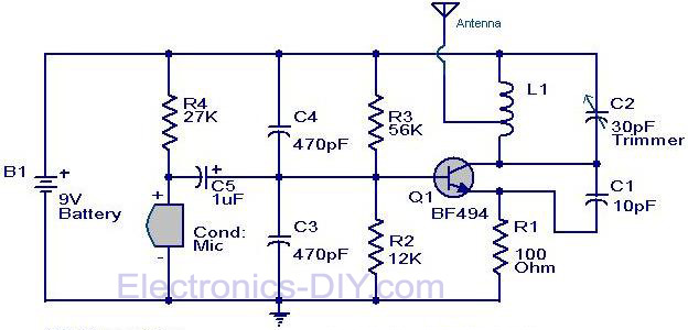
Overall, this simple circuit allows for experimentation with AM transmission and reception, providing insight into the fundamental principles of radio communication. While more complex circuits are used in professional AM broadcasting, this project serves as an educational tool to understand the basics of amplitude modulation and radio frequency transmission.In this project, you will make a simple 3-stage low-power broadcast-type circuit, using a crystal oscillator integrated circuit and an a collector modulated AM oscillator with amplifier. You can connect the circuit to the an electred microphone or amplified dynamic microphone. Using an electred microphone is shown (in gray) in the diagram below. (no amplified dynamic microphone has a to low output voltage to work. at least 100mv is needed). You could also add a LF preamp stage of one transistor to allow connecting a dynamic microphone directly.
You`ll see that you can receive the signal through the air with almost any AM radio receiver. Although the circuits used in radio stations for AM receiving are far more complicated, this nevertheless gives a basic idea of the concept behind a princip 🔗 External reference
Related Circuits
The circuit diagram of a simple FM transmitter utilizing a transistor is presented. While this design may not guarantee exceptional performance or range, it serves as a fundamental example. The circuit employs a general-purpose radio frequency transistor, the BF...
The following circuit illustrates an FM transmitter circuit diagram operating within the 88-108 MHz frequency range. Features include a 1W transmitter of the Tetsuo style. Components involved are capacitors, among others. The FM transmitter circuit operates in the VHF band,...
A resistance temperature sensor (RTD, resistive temperature device) is available in two types: NTC (negative temperature coefficient) and PTC (positive temperature coefficient). Resistance Temperature Detectors (RTDs) are essential components in temperature measurement systems. They operate on the principle that the...
This operational amplifier (opamp) is available at a low cost. The AD8099 is a very fast opamp with a slew rate of 1600 V/µs and features high-impedance inputs with low input capacitance. Its bandwidth is sufficiently large that at...
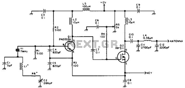
A DSB transmitter is significantly less expensive to construct compared to an SSB transmitter since it does not require filters or phasing networks. This circuit can generate an output of up to 1 watt on the 10-meter band. The...

This is a basic telephone broadcaster or transmitter designed for eavesdropping on telephone conversations. The circuit can also function as a wireless telephone amplifier. A key feature of this phone transmitter is that it derives its power directly from...