
30W Hybrid amplifier 01

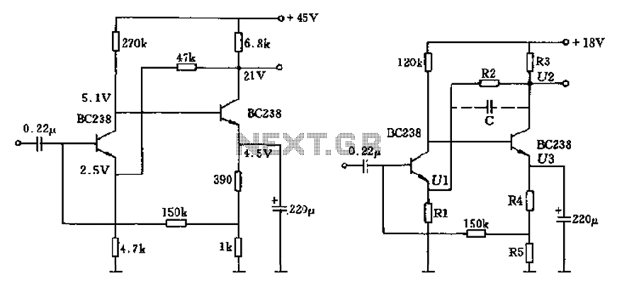
The described pre-amplifier stage utilizes a dual 6F2 pentode configuration to enhance audio signal amplification while minimizing distortion. The SRPP (Shunt Regulated Push Pull) topology is particularly effective for achieving a high dynamic range and low output impedance, which are critical parameters for audio applications.
In this configuration, the 6F2 tubes are arranged in parallel, allowing for increased current handling and improved linearity. The SRPP circuit, while effective, faces limitations in directly driving subsequent amplifier stages due to internal feedback forces. To mitigate this, the long-tail differential inverter is employed. This arrangement not only enhances the overall gain stability but also allows for better control of the output signal characteristics by balancing the load seen by the two triodes.
The choice of resistors R6 and R7, which are intentionally mismatched, plays a crucial role in achieving the desired gain balance between the two tubes. This design consideration ensures that variations in tube characteristics do not adversely affect the output performance. The operating points defined by the diode characteristics and the long-tail circuit parameters are critical for maintaining linear operation across the desired signal range.
Overall, this pre-amplifier stage design exemplifies a sophisticated approach to audio amplification, integrating advanced circuit topologies to achieve superior performance metrics.And the pre-amplifier stage inverter consisting of two three - 6F2 pentode act, the pins are distributed as shown in Figure 2.9, the electrical parameters such as the number sh own in Table 2-3. The tube quite famous, their intensity and resolving power are above 6GH8. The two split 6F2 triode connected in parallel single-ended push-pull SRPP (Shunt Regulated Push Pull) circuit in order to achieve high dynamic, low distortion, and low output impedance. SRPP circuit in the amplifier due to internal forces restrictions, it can not directly push amplifier.
The use of native 6F2 five pole tube portion connected to common cathode differential inverter circuit (often referred to as long-tail type inverter device ), to supplement the SRPP of internal forces in order to correct deficiencies stingy, make compensation long tail of the cathode influence public resistance, the load R6, R7 not get the same resistance (see circuit diagram 2-10), which aims to make the upper and lower inverted tube gain balance. SRPP circuit operating point is provided in three diode output characteristic linear segments (J God F3mA), long tail circuit I, o F2.5mA.
Related Circuits
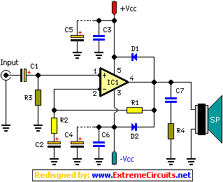
The circuit characteristic involves the elimination of external input resistors, which reduces the influence on the stabilization of the working point. It also employs two DC negative feedback loops. Additionally, the output from the second stage connects to the...
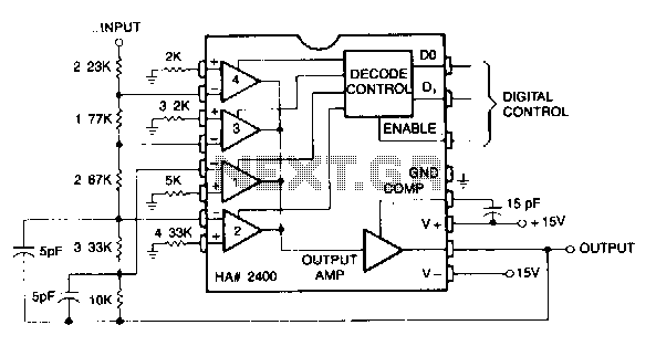
This circuit can be programmed for a gain of 0, -1, -2, -4, or -8. This could also be accomplished with one input resistor and one feedback resistor per channel in the conventional manner, but this would require eight...
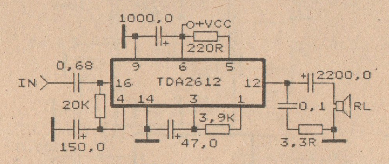
This amplifier circuit is based on the IC TDA2612 produced by Siemens. The minimum voltage required for this circuit is 10 volts, while the maximum voltage is 35 volts DC. The power output is 25 watts with a 4-ohm...
A 2 x 18W Hi-Fi Stereo Power Amplifier is designed using two TDA2030 integrated circuits (ICs). This amplifier features excellent input sensitivity, low distortion, robust operating stability, and comprehensive protection against overloads and output short-circuits. It is suitable for...
This is a simple mini audio amplifier circuit built around a single LM383 integrated circuit, along with several discrete components to support its operation. The circuit is capable of delivering approximately 7W of audio output. It can be constructed...
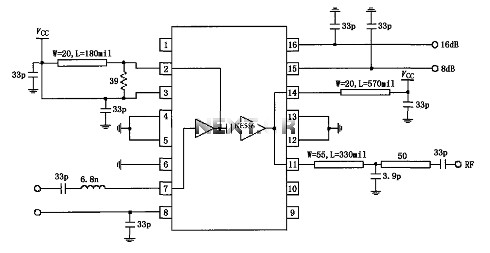
The circuit diagram illustrates the application of a 915MHz RF2155 power amplifier. The radio frequency (RF) signal enters through pin 7, where it is processed by a preamplifier. The output from the preamplifier is further amplified by the power...