
Automatic Room light Control With Bi Directional Visitor Counter

This project integrates various electronic components to create an efficient visitor counting and room lighting control system. The microcontroller serves as the central processing unit, managing inputs from the infrared sensor and controlling outputs to the relay and 7-segment display. The system operates by detecting movement through the IR sensor, which is sensitive to interruptions in the emitted 38 kHz signal. When a person enters the room, the interruption is detected, and the microcontroller increments the count displayed on the 7-segment display.
The monostable multivibrator configuration of the IC555 ensures that each detection event results in a precise timing pulse, which facilitates accurate counting and prevents multiple counts from a single interruption. The use of a relay allows for high-power applications, such as lighting, to be controlled by the low-power microcontroller output. The reset button provides a manual method to clear the count, enabling the system to be reused in different scenarios without manual intervention.
Overall, this circuit exemplifies the application of basic electronic principles in creating a practical solution for modern living, enhancing convenience through automation while maintaining simplicity in design.The objective of this project is to make a controller based model to count number of persons visiting particular room and accordingly light up the room. Here we can use sensor and can know present number of persons. In today`s world, there is a continuous need for automatic appliances with the increase in standard of living, there is a sense of urg
ency for developing circuits that would ease the complexity of life. The IR transmitter will emit modulated 38 kHz IR signal and at the receiver we use TSOP1738 (Infrared Sensor). The output goes high when the there is an interruption and it return back to low after the time period determined by the capacitor and resistor in the circuit.
I. e. around 1 second. CL100 is to trigger the IC555 which is configured as monostable multivibrator. Input is given to the Port 1 of the microcontroller. Port 0 is used for the 7-Segment display purpose. Port 2 is used for the Relay Turn On and Turn off Purpose. LTS 542 (Common Anode) is used for 7-Segment display. And that time Relay will get Voltage and triggered so light will get voltage and it will turn on. And when counter will be 00 that time Relay will be turned off. Reset button will reset the microcontroller. Microcontroller based Visitor Counter. This circuit diagram shows how a 555 timer IC is configured to function as a basic monostable multivibrator. A monostable multivibrator is a timing circuit that changes state once triggered, but returns to its original state after a certain time delay.
It got its name from the fact that only one of its output states is stable. It is also known as a one-shot`. In this circuit, a negative pulse applied at pin 2 triggers an internal flip-flop that turns off pin 7 ²s discharge transistor, allowing C1 to charge up through R1. At the same time, the flip-flop brings the output (pin 3) level to high`. When capacitor C1 as charged up to about 2/3 Vcc, the flip-flop is triggered once again, this time making the pin 3 output low` and turning on pin 7 ²s discharge transistor, which discharges C1 to ground.
This circuit, in effect, produces a pulse at pin 3 whose width t is just the product of R1 and C1, i. e. , t=R1C1. IR Transmission circuit is used to generate the modulated 36 kHz IR signal. The IC555 in the transmitter side is to generate 36 kHz square wave. Adjust the preset in the transmitter to get a 38 kHz signal at the o/p. around 1. 4K we get a 38 kHz signal. Then you point it over the sensor and its o/p will go low when it senses the IR signal of 38 kHz. 🔗 External reference
Related Circuits
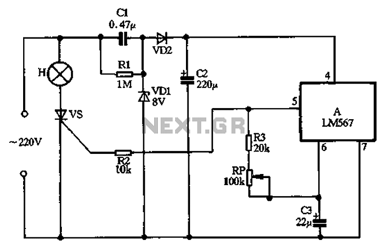
Cl, VDI, VD2, C2 form a simple capacitive step-down voltage regulator circuit with a rectifier output providing approximately 8V DC voltage for the LM567. A 5.6-foot manifold is connected. Resistors R3, RP, and capacitor C3 create an ultra-low frequency...
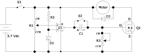
The following circuit illustrates an Airplane Flight Timer Circuit Diagram. Features include switches in the closed position and battery voltage maintained at a safe level. The Airplane Flight Timer Circuit is designed to provide a reliable timing mechanism for monitoring...
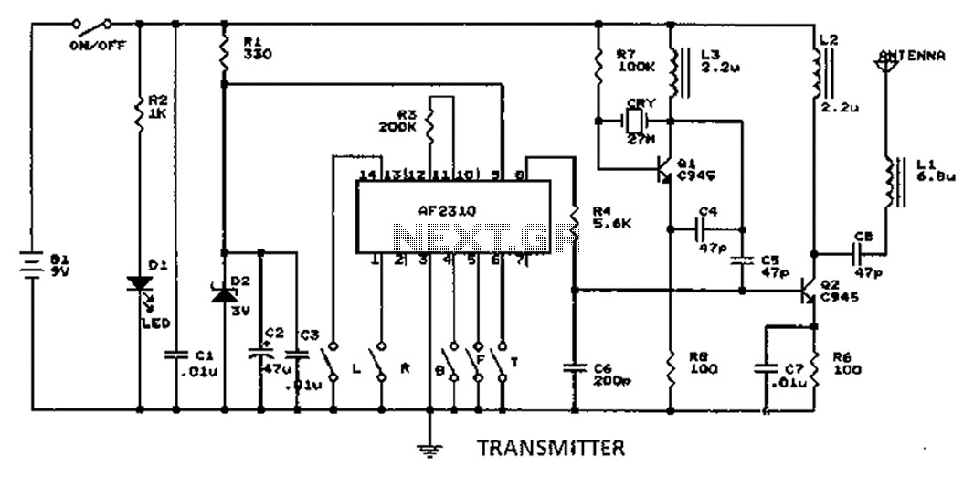
A radio control circuit designed for controlling small motors, similar to a car radio remote control toy, offers seven functions: forward, backward, left, right, left behind, right behind, and stop. The circuit requires a 27.9 megahertz frequency and a...
This circuit is constructed using standard components and can be easily adapted for computer control. By utilizing inexpensive surplus transistors and a stepper motor, the overall cost of the circuit can be maintained at under $10. The described circuit is a...
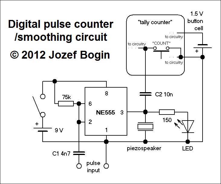
This is a simple yet versatile pulse counting and smoothing integrator circuit featuring an NE555 timer as the waveform shaper and a small LCD display for output. Originally designed for counting pulses from Geiger counters, it includes a piezo...
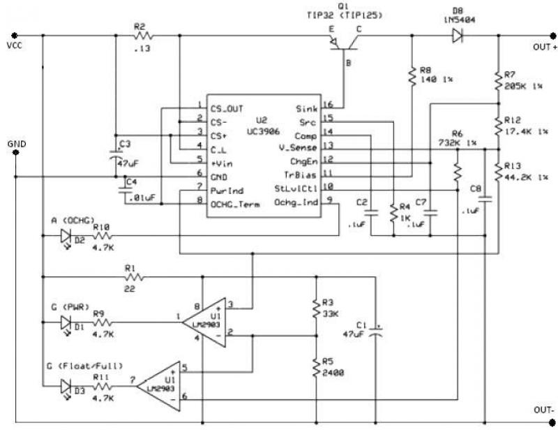
The UC3906 battery charger circuit controller includes all necessary circuitry to manage the charge and hold cycles for sealed lead-acid batteries. This circuit is specifically designed to deliver the appropriate charging voltage and current based on the battery's temperature...