
Thermistor lights lighting delay circuit

The circuit operates based on the thermal characteristics of the PTC thermistor, which exhibits a significant increase in resistance as the temperature approaches its Curie point. Initially, when the circuit is powered on, the thermistor remains cold, allowing current to flow through it and the lamp, resulting in illumination. As the lamp heats up, the temperature of the thermistor rises, leading to an increase in its resistance. This change in resistance effectively reduces the current flowing through the lamp, thereby controlling its brightness and extending the delay time before it turns off.
Adjustable resistor Rz plays a critical role in fine-tuning the delay time. By varying its resistance, the user can change the time it takes for the thermistor to reach its Curie point and thus modify the duration of the lamp's illumination. The value of the capacitor C is also essential, as it influences the charging time and, consequently, the delay time. A larger capacitance will result in a longer delay, while a smaller capacitance will shorten the delay.
The close contact requirement between resistors Rt and R2 ensures that they effectively sense the thermal changes in the circuit. This configuration is vital for accurate temperature measurement and response, allowing the circuit to function reliably under varying operational conditions. The overall design is simple yet effective, providing a practical solution for applications requiring controlled delay timing in lighting systems. Circuit shown in Figure 2-49. The circuit is very simple, cold PTC thermistor element, jump characteristic thermal resistance of the lamp to control delay time. Usually the del ay time is 10 ~ 30s, such as to change the delay time, adjustable Rz, the value of C. R. Adopt a positive temperature coefficient of thermal PTC thermistor, the choice of the Curie point about 80, nominal resistance value at 20 rise when 1500,80 to several thousand Euro to several tens of kilohms. Rt and R2 is required intimate contact.
Related Circuits
The schematic for this project is significantly more complex than previous designs. There are four primary features in the design: (1) the ability to program the PIC microcontroller on the developed board, (2) control of a servo motor, (3)...
The circuit utilizes a 555 timer configured as a multivibrator, where the oscillation frequency is determined by resistors R1, R2, and capacitor C1. The frequency formula is given by fo = 1.443 / ((R1 + R2) * C1). The...
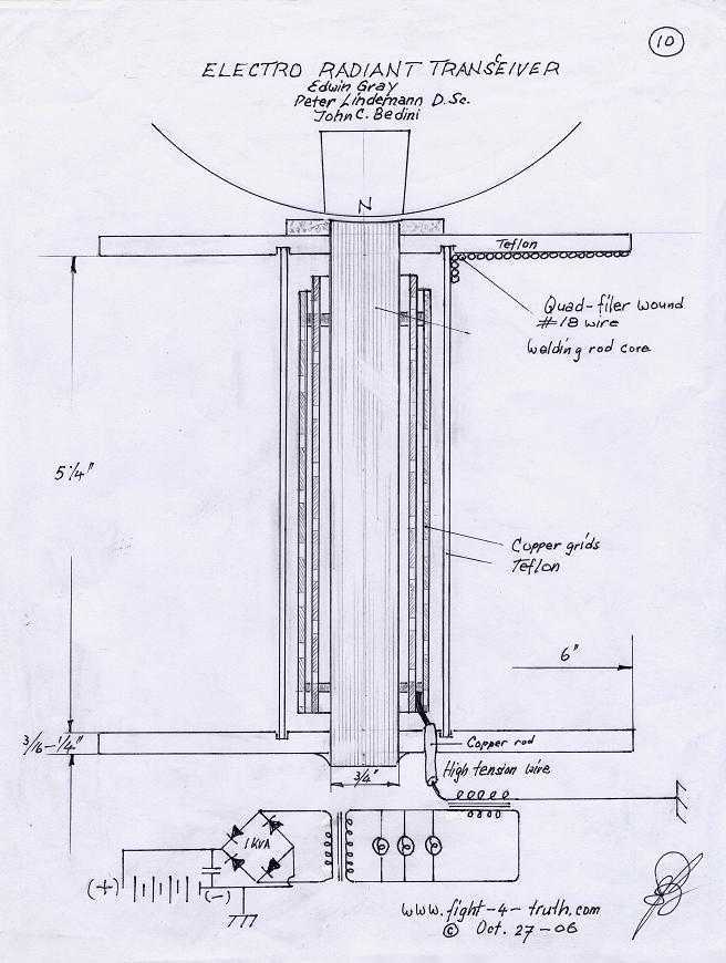
The power is all in the timed switching process. There are two main principles I use of switching the radiant energy the John Bedini way. First, the SG/SSG, Icehouse unidirectional circuit or John Bedini Monopole with the School Girl...
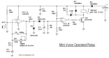
This circuit diagram illustrates a voice-operated relay, which functions similarly to a sound-activated switch circuit. It activates and deactivates the switch based on sound input. The output switch of this circuit is controlled by a relay. The release time...

An AC-coupled unity gain voltage follower operating on a single supply is illustrated. The voltage divider network consisting of resistors R1 and R2 provides a DC voltage equal to half the supply voltage to the non-inverting input of the...
This simple low voltage tester circuit can be used to monitor batteries and other voltage sources for issues, utilizing an LED display and alarm sound. The low voltage tester circuit is designed to provide a reliable method for monitoring the...