
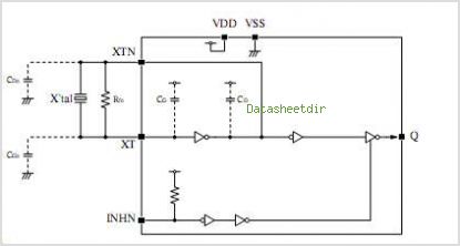
32768 hz quartz oscillator

A watch crystal oscillator is a fundamental component used in various electronic applications, particularly in microcontroller circuits, to provide a stable clock signal. In the context of a PIC microcontroller, the oscillator circuit can be designed using a quartz crystal, which is known for its precise frequency stability.
The circuit typically involves connecting a quartz crystal between the oscillator pins of the PIC microcontroller. The crystal's resonant frequency determines the clock speed of the microcontroller, which is crucial for timing and synchronization in digital circuits. The configuration may include load capacitors connected to the crystal terminals to ensure proper operation and frequency stability.
In this design, since the use of logic gates is avoided, the oscillator function relies solely on the internal oscillator capabilities of the PIC microcontroller, which can utilize the external crystal for generating the necessary clock signal. This approach simplifies the circuit and reduces component count, enhancing reliability and minimizing potential failure points.
The typical values for the load capacitors can be calculated based on the crystal specifications and the microcontroller's requirements, ensuring that the circuit operates within the desired frequency range. It is essential to refer to the specific PIC microcontroller datasheet for accurate pin configurations and recommended capacitor values to optimize performance.
Overall, the implementation of a watch crystal oscillator in a PIC microcontroller circuit is a straightforward yet effective method to achieve precise timing without the complexity introduced by additional logic gates.hi this my 1st post here. topic is a watch crystal oscillator for PIC (microcontroller). i do not want to use logic gates. here the circuit (a thread.. 🔗 External reference
Related Circuits
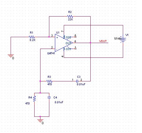
A practical project is being conducted using the LM741 operational amplifier configured as a Wien bridge oscillator. The component values are specified as follows: C1 = C2 = 0.01 µF, R1 = R2 = 3 kΩ, Rf = 2...
International Crystal OF-1 LO oscillator circuit for fundamental-mode crystals that you can find. The International Crystal OF-1 local oscillator (LO) circuit is designed to operate with fundamental-mode crystals, which are widely used in various frequency generation applications. This oscillator circuit...

A voltage-controlled oscillator (VCO) operates similarly to a voltage-to-frequency converter (VFC). Its output frequency is determined by a control voltage input. In the circuit diagram, 'd' represents the amplifier input voltage, which is set to 0.6V, while 'h' denotes...
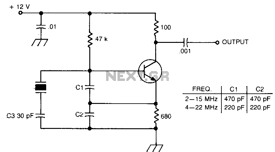
Figures (a) and (b) illustrate two basic oscillator circuits operating at 2 MHz. The circuit design allows for adjustment of the optimal operating point through testing. The two oscillator circuits depicted in the figures utilize different configurations to achieve stable...
SEL2411AA is a sub-package of SEL2410. For a detailed description, please refer to SEL2410. The datasheet for SEL2411AA can be downloaded from the link provided below. By Pericom Semiconductor Corporation. The SEL2411AA is a specialized electronic component that serves as...
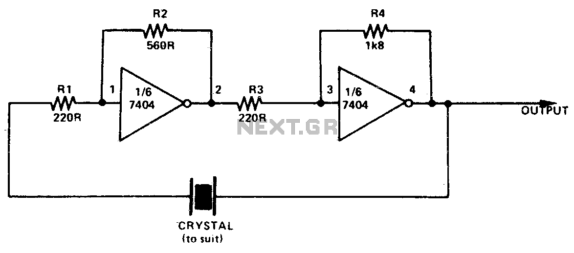
This simple and inexpensive crystal oscillator consists of one-third of a 7404 IC, four resistors, and a crystal. The inverters are biased into their linear regions by resistors R1 to R4, while the crystal provides the necessary feedback. Oscillation...