
The crystal oscillator circuit with frequency in 2MHz

The two oscillator circuits depicted in the figures utilize different configurations to achieve stable oscillation at the desired frequency of 2 MHz. The first circuit may employ a Colpitts or Hartley oscillator design, which is characterized by its use of capacitive and inductive components to establish feedback for oscillation. The second circuit might utilize a phase-shift oscillator configuration, relying on resistive and capacitive elements to create the necessary phase shift for sustained oscillation.
Both circuits incorporate a transistor or operational amplifier as the active component, which amplifies the feedback signal to maintain oscillation. The tuning elements, typically variable capacitors or inductors, facilitate fine-tuning of the frequency to ensure precision at 2 MHz. Testing and adjustment of these components are crucial for achieving the best operating point, as variations in component values can significantly affect the frequency stability and amplitude of the output signal.
Power supply considerations should also be addressed, ensuring that the circuits are powered adequately to prevent distortion or signal degradation. Additionally, output coupling may be implemented to interface with other stages of a system, which could include filtering or impedance matching networks to optimize signal integrity and minimize losses.
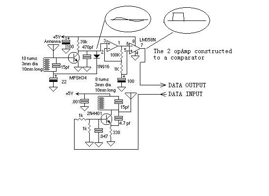
In conclusion, the ability to adjust the operating point through testing is essential for maximizing the performance of these oscillator circuits, making them suitable for various applications in signal generation and modulation.Figure (a) and (b) show the two 2MHZ basic oscillator circuits. According to the circuit structure, it can adjust its best operating point by testing.. 🔗 External reference
Related Circuits
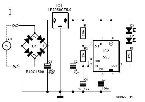
This article is relevant only to readers whose bicycle lights are powered by a dynamo. The regulations regarding bicycle lights in the United Kingdom are stricter than in many other countries, making dynamos a rarity in the UK. For...
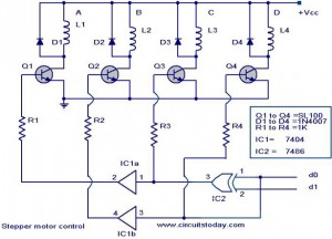
The following circuit illustrates a Stepper Motor Controller Circuit Diagram. This circuit is based on the 7404 IC. Features include a simple stepper motor. The stepper motor controller circuit utilizing the 7404 IC is designed to drive a stepper motor...
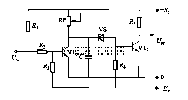
The circuit is a rechargeable short delay control for a conducting pipe, featuring two adjustment potentiometers (RP) that enable the delay time to be set from several hundred milliseconds to several seconds. The rechargeable short delay circuit is designed for...

This 4-channel commutator utilizes the 2N4091 to achieve a low channel ON resistance (approximately 30 ohms) and minimal OFF current leakage. The DM7800 voltage translator is a monolithic device that provides gate drive voltages ranging from 10V to 20V...

A simple battery charger designed for Nickel Metal Hydride batteries that require current-regulated charging. The charger delivers a charging current of 140 mA for efficient battery charging. The power supply section includes a 0-18 volt AC 1 Ampere step-down...
Even including labor, the actual cost of purchasing, stocking, assembly, assembly errors, more expensive PCBs (with additional holes and larger sizes), and the increased difficulty in tuning would likely result in significantly higher expenses. The analysis of costs associated with...