
36 Led Flasher Driver Circuit

The circuit in question employs a basic astable multivibrator configuration using operational amplifiers or timers, which generates a square wave output that can be used to drive multiple outputs. The primary component, U2, acts as a frequency generator, producing a pulsing signal that can be adjusted for different flashing rates.
To enhance the versatility of the circuit, additional outputs can be obtained by modifying the connections of U2. This allows for the integration of multiple LEDs or other light sources, enabling a more elaborate lighting display. The outputs can be connected to transistors or MOSFETs to handle higher current loads, ensuring that the circuit can drive various types of lighting elements, including incandescent bulbs or high-power LEDs.
Power supply considerations are essential for the operation of the circuit. A stable voltage source is required to ensure consistent performance, especially when multiple outputs are activated simultaneously. Additionally, decoupling capacitors should be employed near the power pins of the ICs to minimize noise and improve stability.
The design can also include a variable resistor or potentiometer in the timing circuit to allow users to adjust the flashing speed according to their preferences or specific application requirements. By carefully selecting the timing components (resistors and capacitors), the frequency of the flashing can be tailored, providing further customization for different scenarios.
In summary, this three-bell animation circuit is a flexible and adaptable design that can be repurposed for various flashing applications beyond its original intent. Its ability to provide multiple outputs and adjustable flashing rates makes it suitable for a wide range of decorative and functional lighting projects. Originally intended as a 3-bell animation circuit for Christmas decorations, the circuit can be used for many other purposes that require a flasher of this kind. By re-connecting U2 (see the data manual), more than three outputs can be be obtained.
Related Circuits
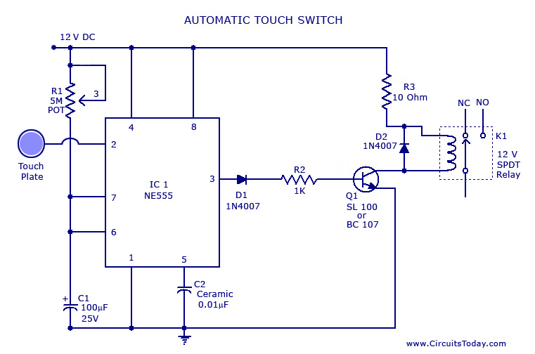
A touch switch circuit schematic utilizing a 555 integrated circuit (IC). When the touch plate is activated, a relay is switched ON for a predetermined duration, which can also be adjusted. The touch switch circuit employs a 555 timer IC...
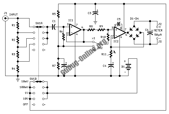
This design circuit is used to activate circuitry and an analog meter for sensitive DC current measurements. A subsequent inquiry raised the possibility of measuring AC microamperes, which inspired the idea for this circuit. The circuit is designed to facilitate...
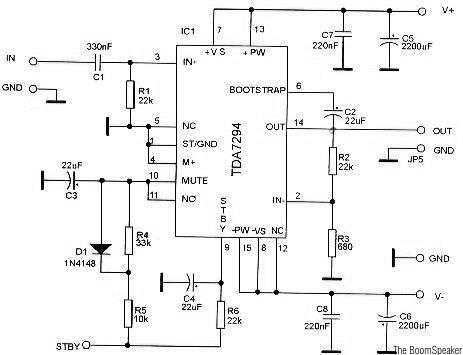
The TDA7294 is a monolithic integrated circuit housed in a Multiwatt15 package, designed to deliver high output power of up to 100W. It is intended for use as an audio Class AB amplifier in high-fidelity applications. The TDA7294 is a...
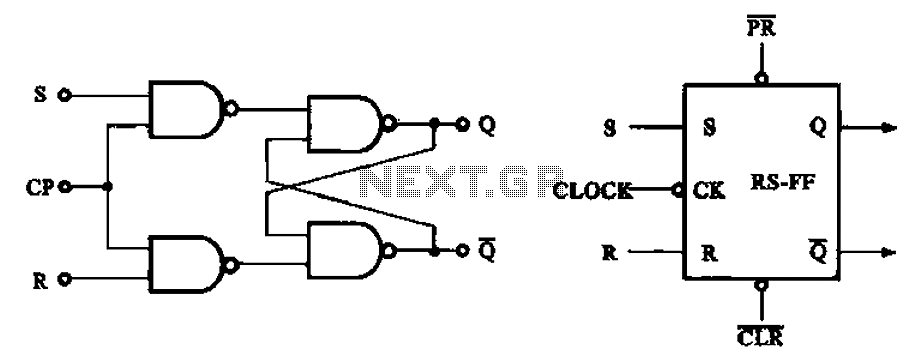
The asynchronous RS flip-flop mentioned earlier is not synchronized with the system clock signal. In contrast, the synchronous RS flip-flop incorporates synchronization, allowing it to operate in conjunction with the clock signal. Figure (a) illustrates the circuit configuration of...
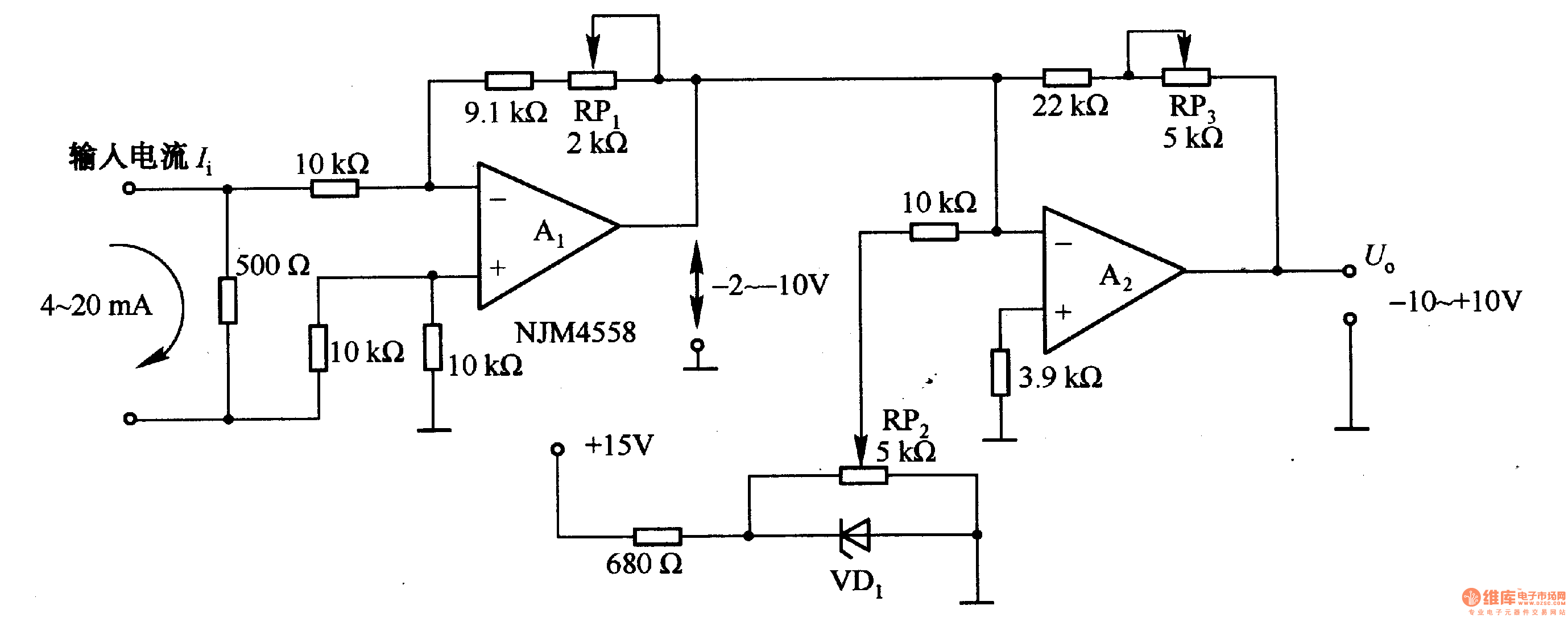
Figure 1-42 (a) is a voltage/current conversion circuit that converts a 0-10V input voltage into a 4-20mA output current. Adjusting resistor RP2 can set the input voltage (Ui) to 0V, resulting in an output current (I) of 20mA; similarly,...
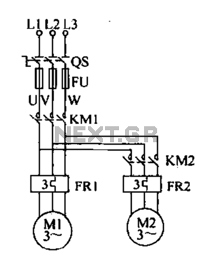
Delay starting a motor control circuit The motor control circuit designed for delayed activation incorporates a timing mechanism that ensures the motor does not start immediately upon receiving power. This is particularly useful in applications where a staggered startup...