
3w fm transmitter

The FM transmitter circuit is designed to modulate audio signals onto a carrier frequency within the VHF band, specifically between 90 and 110 MHz, which is suitable for FM broadcasting. The output power of 3 to 3.5 watts is adequate for short-range transmission, making it ideal for personal or experimental use.
The main components of the circuit typically include an oscillator, modulator, and amplifier stages. The oscillator generates the carrier frequency, while the modulator superimposes the audio signal onto this carrier wave, creating frequency modulation. The amplifier then boosts the modulated signal to the desired output power level.
In terms of circuit stability, while the basic design may function adequately, the implementation of a Phase-Locked Loop (PLL) can significantly improve frequency stability and reduce drift. A PLL can lock the oscillator frequency to a stable reference, ensuring consistent performance over time and varying environmental conditions. This addition can be particularly beneficial in applications where frequency precision is crucial.
The schematic may also include additional components such as filters to suppress unwanted harmonics, ensuring compliance with broadcasting regulations. Antenna matching networks may be integrated to optimize the transmission efficiency, allowing for effective radiation of the modulated signal.
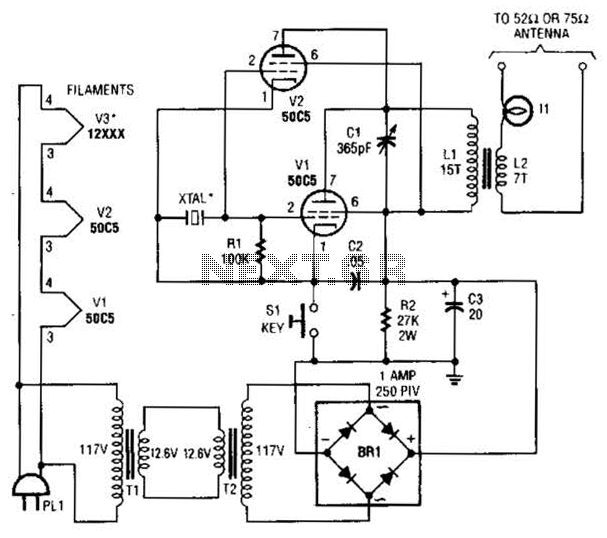
Overall, this FM transmitter circuit serves as a foundational design for those looking to explore frequency modulation transmission, with the potential for enhancements through advanced techniques such as PLL implementation.This is the schematic for an FM transmitter with 3 to 3.5 W output power that can be used between 90 and 110 MHz. Although the stability isn`t so bad, a PLL can be used on this circuit.. 🔗 External reference
Related Circuits
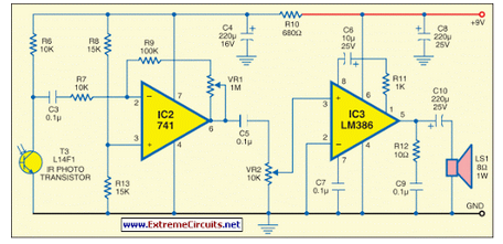
The transmitter provides an optical link (infrared) for headphones. Three infrared LEDs (IR) are powered by T1, with P1 used to adjust the current level. The current consumption of this headphones infrared transmitter is approximately 60mA at 9V. The infrared...
This circuit generates audio musical notes that can be heard from a distance of up to 10 meters. The circuit is divided into two parts: an infrared (IR) music transmitter and a receiver. The circuit operates on the principle of...
This low-power video transmitter is designed for remote control (R/C) applications, surveillance, or amateur radio purposes. It utilizes seven transistors within a crystal oscillator-multiplier RF power amplifier chain, along with a high-level video modulator. A supply voltage of 9...
These two tank circuits appear to broaden the operating spectrum. The accompanying information sheet indicates that when both circuit stages oscillate at the same frequency, the power output reaches its maximum. This suggests that if the tunable tank circuit...
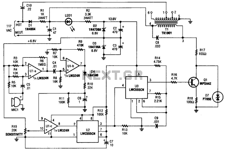
The baby-alert transmitter is constructed using an LM324 quad operational amplifier (U1), two LMC555CM CMOS oscillator/timers (U2 and U3), along with several supporting components. The transmitter activates upon detecting sound at MIC1, emitting a signal. Its operational frequency is...
This SMD FM transmitter operates within a frequency range of approximately 80 to 115 MHz. Under optimal conditions, the signal can be received at a distance of around 200 meters. Although it is classified as low-power, its use may...