
A small FM transmitter (SMD)s
s")
The SMD FM transmitter circuit is designed to operate effectively within the specified frequency range, making it suitable for various short-range audio transmission applications. The transmitter utilizes an electret microphone, which serves as the audio input source. The microphone's output is fed into a pre-amplifier stage, where resistor R4 plays a crucial role in adjusting the gain. This allows for fine-tuning of the audio signal strength, ensuring optimal performance based on the specific characteristics of the chosen microphone.
The circuit's LC components, which include inductors and capacitors, are pivotal in determining the frequency stability and efficiency of the transmitter. The quality factor (Q) of these components can significantly influence the transmission range and signal clarity. As such, careful consideration must be given to the selection of SMD components, as off-the-shelf parts may not provide the desired performance. If the Q factor is found to be inadequate, re-biasing the final amplification stage may be necessary to enhance signal integrity and transmission range.
For the inductor, the ECM45T Series Inductor is recommended due to its suitability for RF applications. This component is designed to deliver reliable performance in high-frequency circuits, contributing to the overall effectiveness of the transmitter. The careful selection and configuration of these components are essential for achieving the desired operational characteristics of the SMD FM transmitter, ensuring compliance with local regulations while maximizing transmission capabilities.This SMD FM transmitter has an operating frequency of about 80 to 115MHz. Under reasonable circumstances you will be able to receive its signal at a distance of about 200 meters. Although it is low-power, it might be illegal in your part of the planet. Depending on the electret microphone you use, you might have to tweek R4 to set the gain of the pre-amplifier. Depending on the Q of the LC-part (usually not very good when using off-the-shelf SMD parts) you may also have to re-bias the end stage of the circuit. For the coil you can use a ECM45T Series Inductor. 🔗 External reference
Related Circuits
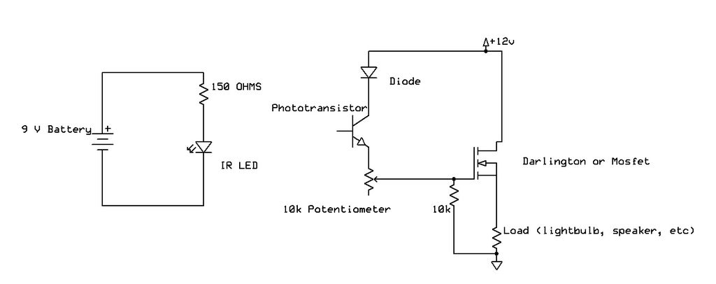
Recently, samples of IR LEDs and a corresponding IR phototransistor were acquired. A project was initiated to utilize these components. The project involves the integration of infrared (IR) LEDs with an IR phototransistor to create a simple optical communication system...
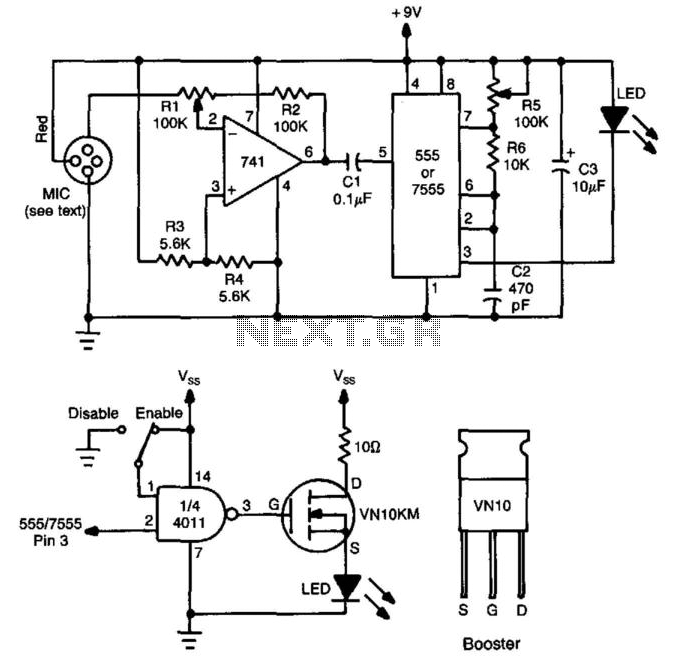
This circuit utilizes a 741 audio amplifier, which is connected to an amplified microphone, an FM modulator, and a CMOS timer functioning as a voltage-controlled oscillator (VCO). The timer output drives an LED, which is pulsed to produce an...
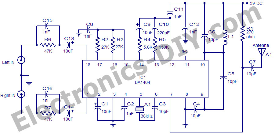
The circuit utilizes the BA1404 integrated circuit from ROHM Semiconductors. The BA1404 is a monolithic FM stereo modulator that incorporates a stereo modulator, FM modulator, and RF amplifier circuitry. This FM transmitter operates within the frequency range of 76...
This 2-meter 144 MHz fox hunt transmitter is utilized in amateur competitions where a concealed transmitter is to be "hunted" using primarily homemade receivers. The 2-meter 144 MHz fox hunt transmitter is designed for use in amateur radio competitions, commonly...
When the power supply reaches the circuit and the input signal is applied, the sound signal is processed through capacitor C1 and resistor R1 for signal coupling and noise reduction. The modified signal then reaches pin 3 (non-inverting) of...
A Tesla Coil can be understood as a high-power radio frequency transmitter with an inefficient antenna. The secondary coil functions as a significantly shortened quarter-wave antenna. The Tesla Coil is an electrical resonant transformer circuit that is designed to produce...