
4 Band Double Tuned Preselector

The described circuit functions as a radio frequency preamplifier designed to enhance weak RF signals received from antennas. The choice of antennas, such as a long wire or a loop antenna, allows for flexibility in signal reception and can be tailored based on the specific application and environment.
The preamplifier's frequency range, extending from 550 kHz to 30 MHz, covers both Medium Wave (MW) and Shortwave (SW) bands, making it suitable for various radio communications and amateur radio applications. The inclusion of an input switch (S1) allows for efficient selection of the appropriate tuning coils via relays, optimizing the circuit's performance for different frequency bands.
The double-tuned configuration of the preamplifier is critical for achieving higher selectivity and gain. By employing two IFT (Intermediate Frequency Transformer) coils for each RF range, the circuit can effectively filter and amplify the desired signals while minimizing interference from unwanted frequencies.
The use of a double-gate MOSFET in the circuit enhances its performance by providing high input impedance, which is essential for preventing signal loss from the antenna. The gate G1 receives the RF input, while gate G2 is utilized for gain control, allowing for adjustments based on the signal strength. The output is extracted from the drain terminal of the DGMOSFET, which is where the amplified signal is available for further processing or transmission.
Overall, this circuit design exemplifies effective techniques in RF amplification and tuning, making it a valuable component in radio frequency applications.The circuit requires an RF input which can be from a longwire or a loop antenna. The Preamplifier has a range from 550kHz (Medium Wave) up to 30 MHz in the SW band. The input Switch S1, applies voltage to a set of relays which switch in the appropriate coils. The preamplifier is double tuned on the input having two IFT coils for each RF range, inp ut applied to G1 of a double gate MOSFET. Gain control is applied to G2 and the output is taken from the DGMOSFET drain terminal. Click here for a picture of David`s MW loop. Click here to view a finished picture of this project. 🔗 External reference
Related Circuits
A band-pass filter permits only signals within a specified frequency range to pass through, while attenuating or suppressing those outside this range. This is characterized by a lower frequency limit and an upper frequency limit. A typical implementation is...
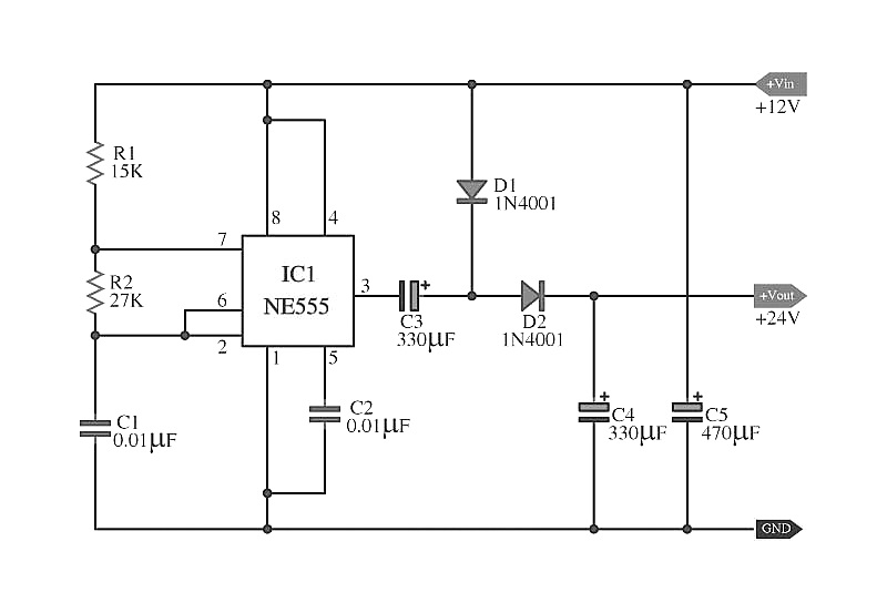
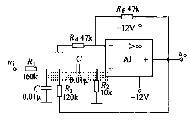
The capacitors C5 work in conjunction with IC1, while the resistors R1 and R2, along with capacitors C1, form an astable multivibrator square wave generator. This generator outputs a frequency of approximately 2 kHz from pin 3 of IC1....
A bandpass filter allows a specific range of frequencies to pass while rejecting frequencies that fall outside the upper and lower limits of the passband. The frequencies that are permitted to pass are referred to as the passband, which...
Electronics tutorial on the passive band pass filter circuit, which includes the passive RC band pass filter's first-order frequency response and Bode plot. The passive band pass filter circuit is a fundamental electronic component that allows signals within a specific...
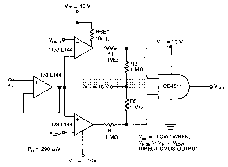
The detector utilizes three sections of an L144 and a DC4011 type CMOS NAND gate to create a very low power voltage monitor. If the input voltage, Vin, is above Vhigh or below Vlow, the output will be a...
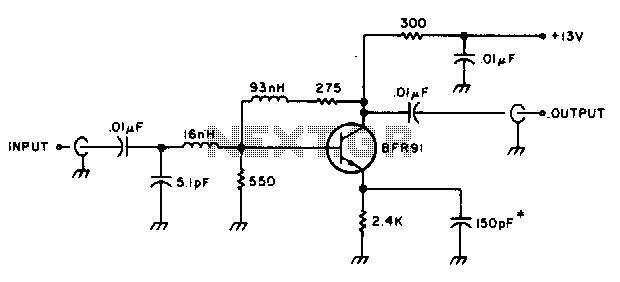
The amplifier delivers a gain of 10 dB across a frequency range of 10-600 MHz and features a 1-to-1 impedance match at 50 ohms. The BFR91 transistor exhibits a noise figure of 1 dB at 500 MHz. The circuit...