
4-Channel Mixer

The mixer circuit utilizes the SSM2024, which is a quad transconductance amplifier that allows for high precision and low distortion in audio applications. The four transconductance amplifiers are configured to provide a differential input, enhancing the circuit's ability to reject common-mode signals and improve overall performance. The 200-ohm impedance to earth is crucial for maintaining signal integrity and minimizing noise, which is achieved through the careful selection of resistors R5 to R8. These resistors not only establish the necessary impedance but also work as part of a potential divider, ensuring that the input signal levels are appropriately managed.
The design stipulates that the nominal input signal is set to 1V, which is a standard level in audio systems. The distortion figures indicate that the mixer performs well within acceptable limits, with a maximum of 1% distortion at nominal levels and significantly lower distortion at reduced levels. This performance is essential for high-fidelity audio applications where clarity and accuracy are paramount.
The control inputs of the CDAs allow for dynamic adjustment of gain, with the amplification directly proportional to the current supplied. This design feature is advantageous because it allows for real-time control over the output characteristics of the mixer. The virtual earth configuration simplifies the design, as it allows for straightforward calculations for the bias resistors needed to convert the current-driven inputs into voltage-driven inputs.
The summation of output currents from the amplifiers through direct pin connections exemplifies a simple yet effective approach to combining signals. This method minimizes additional components and potential points of failure, promoting reliability in the circuit. The current-to-voltage converter IC2 plays a critical role in translating these summed currents into a usable output voltage, which can be interfaced with subsequent stages in an audio processing chain. The selection of resistor R13 to maintain unity gain for IC2 is a strategic decision that ensures the output voltage remains proportional to the input, preserving the integrity of the signal throughout the processing chain. The proposed mixer is designed around four current-driven transconductance amplifiers contained in an SSM2024 from Precisio n Monolithics. To obtain a low offset and high control rejection, the four inputs should have an impedance to earth of about 200 . These impedances are obtained from resistors R5 through R8, which also form part of a potential divider at each input.
With the values in the diagram, the nominal input signal is 1V (0 dBV). Distortion at that level is about 1%; at lower levels, it is not more than 0.3%. The amplification of the current-driven amplifiers (CDAs) is determined by the current fed into the control inputs. These inputs form a virtual earth so that calculating the values of the bias resistors (to transform the inputs into voltage-driven inputs) is fairly simple.
The output currents of the amplifier are summed by simply linking the output pins. The current-to-voltage converter, IC2, translates the combined output currents into an output voltage. The value of R13 ensures that the amplification of IC2 is unity.
Related Circuits
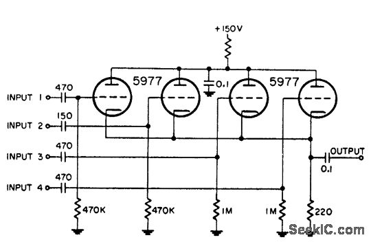
This circuit is utilized for combining four distinct positive-polarity marker pulses in a radar system. The reference for this information is the "Handbook Preferred Circuits Navy Aeronautical Electronic Equipment," Volume 1, Electron Tube Circuits, published in 1963, page N4-1. The...
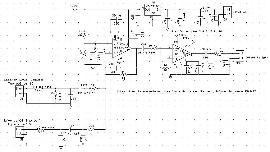
The audio mixer allows for easy comparison of various receivers by adjusting the gain controls without the need for switching. This setup simplifies A/B comparisons since all receivers are connected to the same antenna. Previously, different speakers were used...
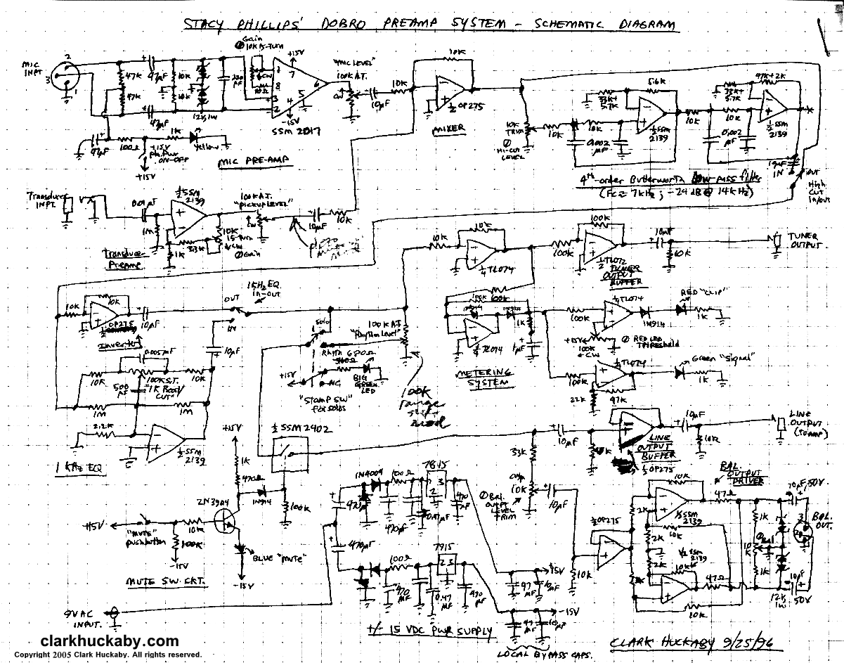
A stomp-box was designed and built for Grammy-winning resophonic guitar player Stacy Phillips. He typically uses two transducers on his Dobro-style instruments: a piezo element mounted internally and a gooseneck-mounted electret microphone positioned approximately one inch above the resonator...
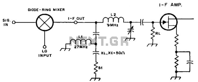
By inserting a high-pass filter section in the intermediate frequency (IF) lead, this mixer is terminated at all frequencies except for the IF, which results in improved intermodulation distortion (IMD) for other mixer products. In this example, the high-pass...
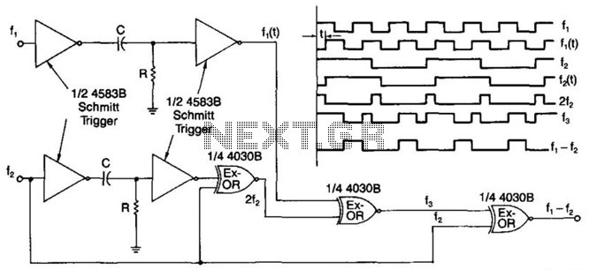
A simple digital mixer uses two dual-Schmitt triggers (4583B) and three exclusive-OR gates, incorporating an RC time-delay circuit to allow for easy adjustment of the output signal pulse width. The exclusive-OR gates can also function independently as a symmetrical...
The MAXQ7667 smart system-on-a-chip (SoC) offers a time-of-flight ultrasonic distance-measuring solution. This device is designed for applications that require measurement of large distances with weak input signals or the identification of multiple targets. The MAXQ7667 achieves a high signal-to-noise...