
Mixer Diplexer

The described circuit utilizes a high-pass filter to enhance the performance of a mixer by mitigating intermodulation distortion (IMD). The implementation of the high-pass filter in the IF lead serves to block lower frequency signals while allowing higher frequency signals to pass through. This selective filtering is achieved through the use of an inductor (L1) and capacitors arranged in a configuration that establishes a cutoff frequency at 28 MHz.
In the schematic, the inductor L1 is connected in series with the IF lead, while capacitors are connected to ground. This configuration creates a high-pass filter that ensures signals below 28 MHz are attenuated. The choice of components, particularly the values of L1 and the capacitors, should be selected based on the desired cutoff frequency and the specific impedance of the mixer circuit to ensure optimal performance.
The termination of the mixer at frequencies above the cutoff is crucial as it minimizes reflections and ensures that the mixer operates efficiently within its intended frequency range. This design approach not only enhances the linearity of the mixer but also improves overall signal integrity, making it suitable for high-performance applications in communication systems where clarity and precision are paramount.
In summary, the integration of a high-pass filter in the IF lead of a mixer circuit significantly contributes to reducing unwanted distortion and optimizing the mixer’s performance across its operational frequency range. By inserting a high-pass filter section in the IF lead, this mixer is terminated at all frequencies, besides the IF, for oth er mixer products, which results in improved IMD. In this example, high-pass filter section Ll and capacitors cut off below 28 MHz. Above this frequency, the mixer is terminated.
Related Circuits
The foundation of an audio mixer is an inverting summing circuit. In practical audio mixers, a single-supply voltage is rarely utilized. To enhance dynamic range, ... The inverting summing circuit serves as a fundamental building block in audio mixing applications,...
This project involves a simple circuit designed to mix two or more audio channels into a single channel, such as converting stereo audio into mono. The circuit is capable of accommodating multiple input channels while maintaining low power consumption....
A 183.6 MHz SAW filter is utilized in a CDMA application. The S-parameter of the SAW filter is employed to simulate the interaction with the mixer. An example is provided using the SAWTEK 855893 SAW filter. This application note...
This technical note focuses on determining the system specifications of a CDMA receiver to establish practical specifications for a low noise amplifier and down converter. The design of a CDMA (Code Division Multiple Access) receiver necessitates a comprehensive understanding of...
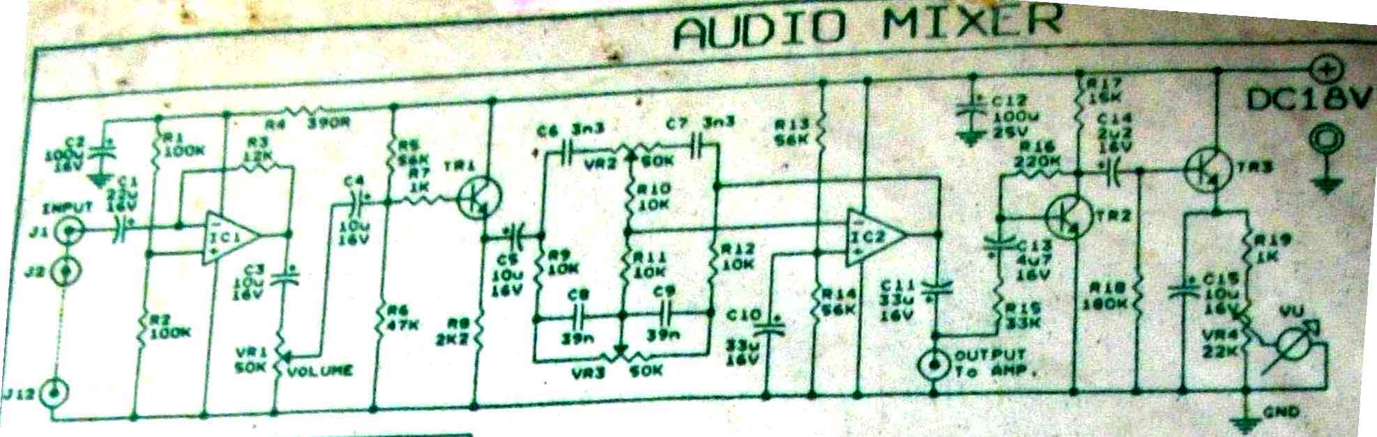
This is audio mixer circuit. The circuit is for one channel input, if you need, for example 5 channel mixer, then you need to build 5 similar circuits. The audio mixer circuit described is designed to handle a single channel...
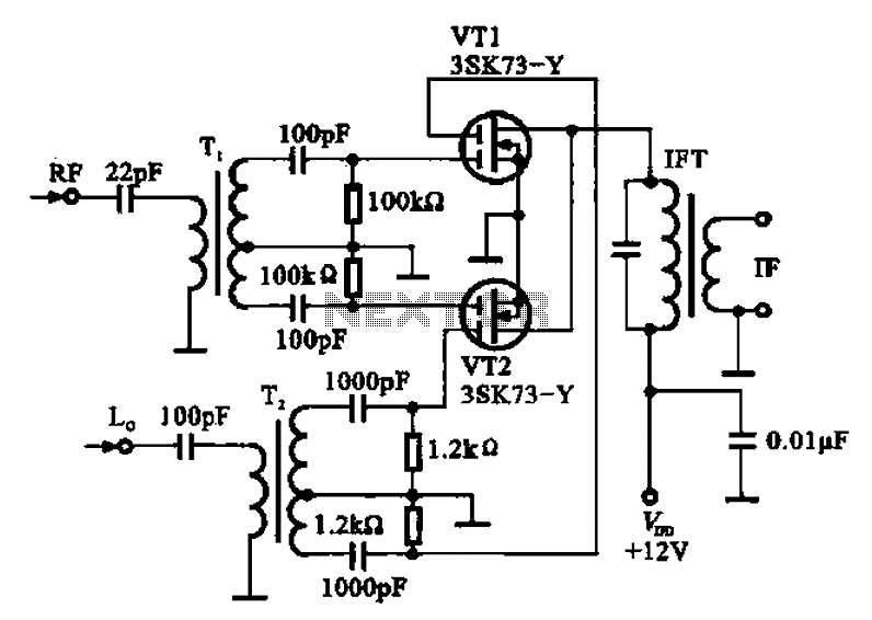
A balanced mixer circuit is illustrated using two dual-gate field effect transistors (FETs). The RF signal is coupled to the gates of these transistors through an input signal transformer (T1). Additionally, a local oscillation signal is introduced to the...