
4-key keyboard using ATtiny85

The 1-key keyboard project utilizes the ATTiny microcontroller, a compact and efficient device suitable for a variety of embedded systems applications. The primary function of this project is to create a simple input mechanism using a single key, which can be employed in various scenarios such as triggering events, sending signals, or controlling devices.
The circuit design typically involves connecting a push-button switch to one of the digital input pins of the ATTiny microcontroller. When the button is pressed, it sends a signal to the microcontroller, which can then be programmed to execute a specific function, such as lighting an LED, sending a signal to another device via a communication protocol, or activating a relay.
To ensure reliable operation, a pull-up resistor is often included in the circuit. This resistor connects the input pin to the positive supply voltage, keeping the pin in a high state when the button is not pressed. When the button is pressed, the input pin is connected to ground, resulting in a low state. Debouncing techniques may also be implemented in the software to prevent false triggering due to mechanical bouncing of the switch contacts.
Power supply considerations are crucial for the ATTiny microcontroller, which typically operates within a voltage range of 1.8V to 5.5V. A simple battery or a regulated power supply can be used to provide the required voltage. The microcontroller can be programmed using a suitable development environment, with code that defines the behavior of the system based on the button press.
In summary, the 1-key keyboard project serves as a practical application of the ATTiny microcontroller, demonstrating its versatility and effectiveness in creating simple yet functional electronic devices.A good while back, I made the 1-key-keyboard project. Ever since it has always been in the back of my mind that the ATTiny microcontroller. 🔗 External reference
Related Circuits

The Wien bridge oscillator utilizes a balanced Wien bridge as its feedback network. Two-stage common source amplifiers provide a 360-degree phase shift to the signal. The attenuation of the bridge is calculated to be 1/3 at the resonant frequency....
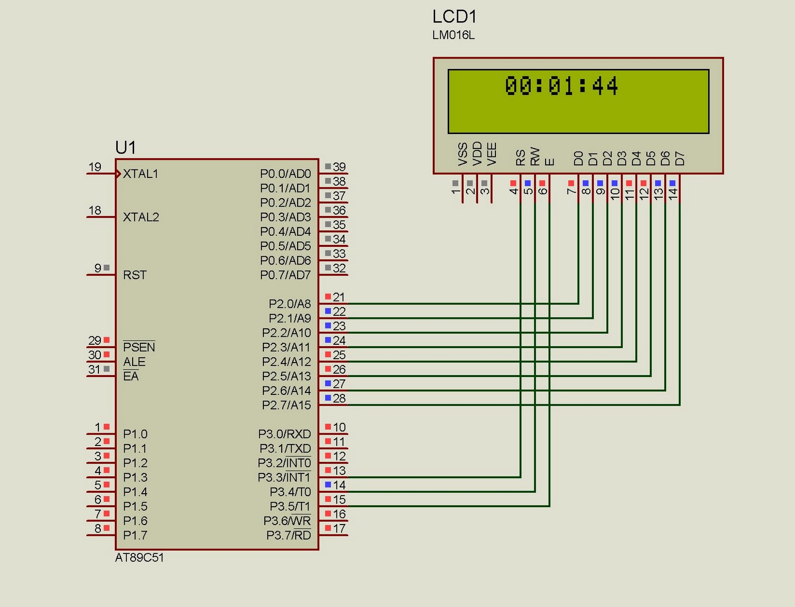
This project implements a real-time clock using the 89C51 microcontroller. The clock's data format is hours:minutes:seconds, which is displayed on a 16x2 LCD. The code has been tested and compiled using the Keil uVision compiler. The circuit diagram for...

By utilizing a high-gain, high-impedance operational amplifier, it is possible to construct a long time delay circuit using a resistor-capacitor (RC) configuration, as it allows for high... An operational amplifier (op-amp) is a versatile component widely used in electronic circuits,...

The LTC3810-5 synchronous step-down switching regulator controller allows for the design of a straightforward 12-volt switching power supply electronic project with minimal external components. This controller can directly reduce voltages from up to 60V, making it suitable for telecommunications...

This circuit is a touch switch circuit, similar to a touch door alarm. It utilizes a 555 timer as the core component of the touch switch circuit. The operation begins when the plate is touched, triggering the 555 timer....
%2BCircuit%2Bdiagram%2Busing%2BCD4047%2Band%2BIRFZ44%2Bpower%2BMOSFET.png)
This simple low-power DC to AC inverter circuit converts 12V DC to either 230V or 110V AC. By making simple modifications, it is also possible to convert 6V DC to 230V AC or 110V AC. This inverter can be...