
touch switch circuit using 555 ic

The touch switch circuit is designed around the versatile 555 timer IC, which is configured in a monostable mode to achieve the desired functionality. When a conductive object, such as a finger, makes contact with the touch plate, it causes a momentary change in voltage at the trigger pin (pin 2) of the 555 timer. This change triggers the timer, resulting in a high output at pin 3.
The LED and buzzer connected to this output serve as indicators, providing both visual and audible feedback. The specific duration for which the LED and buzzer remain active is governed by the time constant, which is determined by the resistor and capacitor values connected to pins 6 and 7. The time period (T) can be calculated using the formula:
T = 1.1 × R × C
where R is the resistance in ohms and C is the capacitance in farads. In this circuit, the presence of the 10 MΩ resistor at pin 2 ensures that the circuit responds effectively to even the slightest touch, enhancing its sensitivity. This characteristic makes the touch switch suitable for various applications, including security systems, home automation, and interactive displays.
The overall design of the circuit can be represented in a schematic, which includes the 555 timer, the touch plate, the LED, the buzzer, and the associated resistors and capacitors. Proper placement of these components is crucial for achieving optimal performance and reliability. Additionally, ensuring that the power supply is stable and within the specifications of the 555 timer is essential for the circuit’s functionality.This is a circuit for touch switch circuit. This circuit is almost same with touch door alarm. This circuit uses a 555 timer as the bases of the touch switch circuit. This is the figure of the circuit. The operation of this circuit is begin, when the plate is touched the 555 timer is triggered and the output on pin 3 goes high turning on the LED a nd the buzzer for a certain period of time. The time that the LED and the buzzer is on is based on the values of the capacitor and resistor connected to pin 6 & 7. The 10 M resistor is on pin 2 causes the circuit to be very sensitive to the touch. 🔗 External reference
Related Circuits

A multivibrator is an electronic circuit used to implement a variety of simple two-state systems such as light-emitting diodes, timers, and flip-flops. The monostable multivibrator will create a condition in which one of the states is stable. A multivibrator circuit...
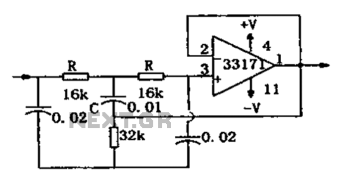
The trap circuit utilizes a high-performance operational amplifier, MC33171, to create the trap. This device features a wide bandwidth and high conversion rate. The component values can be modified by adjusting the capacitance of capacitor C and the resistance...

The ADSP-2103 and ADSP-2105 are digital signal processors that interface with the AD7714. When the output is active, the ADSP-2103/2105 configuration includes the RFS non-TES non-terminal set to a low level, while the SCLK terminal is configured for serial...
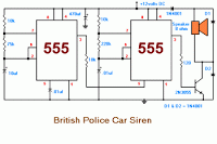
The 555 timer on the right is configured as an alarm sound generator, while the second 555 timer on the left operates as a 1 Hz astable multivibrator. The output from the left timer modulates the frequency of the...
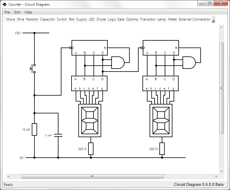
This is Circuit Diagram 0.1 Alpha Software, available for free download and open source. The Circuit Diagram 0.1 Alpha Software is designed as an intuitive platform for creating and editing electronic circuit schematics. It provides users with a variety of...
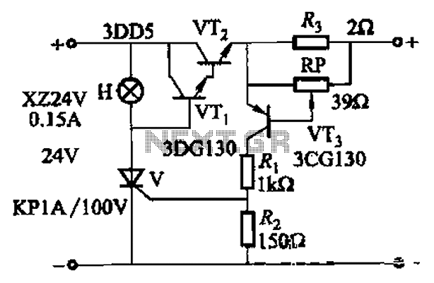
By adjusting Ro or RP, the current setpoint can be modified. The circuit illustrated in Figure 14-98 features overcurrent protection using a thyristor and transistors VTi and VT2, which immediately cut off the power when an overcurrent condition is...