
4-Way Logic Probe

This logic probe is designed to provide a visual indication of digital signal levels across four separate channels, making it a versatile tool for troubleshooting and analyzing digital circuits. The use of quad comparators allows for efficient signal processing, enabling the probe to accurately interpret and display the state of the input signals.
The configuration of the SI and SIB pins allows the user to adjust the threshold levels for detecting logic high and low states, accommodating both TTL (Transistor-Transistor Logic) and CMOS (Complementary Metal-Oxide-Semiconductor) technologies. This flexibility is essential for users who work with various digital logic families, as it ensures compatibility and accurate readings.
The biasing resistors R6 through R13 play a critical role in the operation of the logic probe. By preventing false high indications in the presence of open circuits, these resistors enhance the reliability of the probe's readings. This feature is particularly important in circuit debugging, where open connections can lead to misleading diagnostics.
The bicolor LEDs provide immediate visual feedback on the state of the input signals. The distinct colors for high and low states, along with the capability to display intermediate colors for pulsing signals, allow users to quickly assess signal activity. The specification of a duty cycle between 30% and 70% for pulsing signals ensures that the probe can effectively represent varying signal conditions, making it suitable for real-time monitoring of digital waveforms.
Overall, this logic probe is an essential instrument for electronics engineers and technicians, providing a straightforward and effective means of visualizing digital signals across multiple channels. Its design considerations ensure accurate, reliable performance in a variety of applications, from basic circuit testing to more complex digital system diagnostics. This logic probe has four channels and uses two IF quad comparators to drive four bicolor LEDs. SI and SIB program the co mparator trip levels for TTL and CMOS. R6 through R13 bias the probe inputs to prevent the probe from indicating a high for an open circuit. An open circuit will produce an off indication on the LED. The LEDs will indicate one color for high, the other color for low, and intermediate colors for pulsing (assuming a duty cycle between 30 and 70%).
The color that corresponds to high or low depends on how you connect the LEDs.
Related Circuits
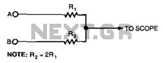
This simple resistor circuit can be used to trick an oscilloscope into displaying two logic signals on one channel. By selecting R2 to be twice the value of R, the oscilloscope trace will show one of four distinct analog...
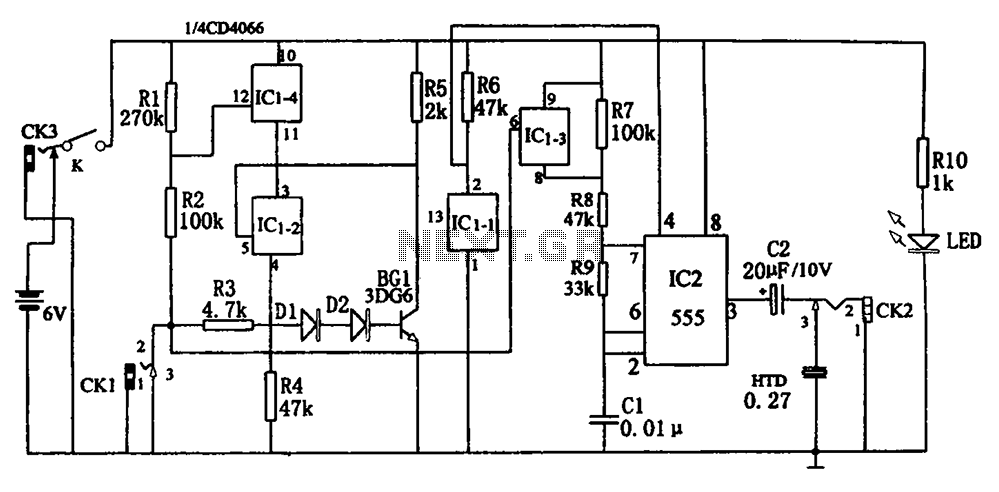
The circuit, illustrated in Figure five, employs a tri-state logic pen audio circuit. It primarily consists of a multivibrator, a four-way switch (CD4066, IC1), and several RC components. The multivibrator (555, IC2), along with resistors R7, R8, R9 and...
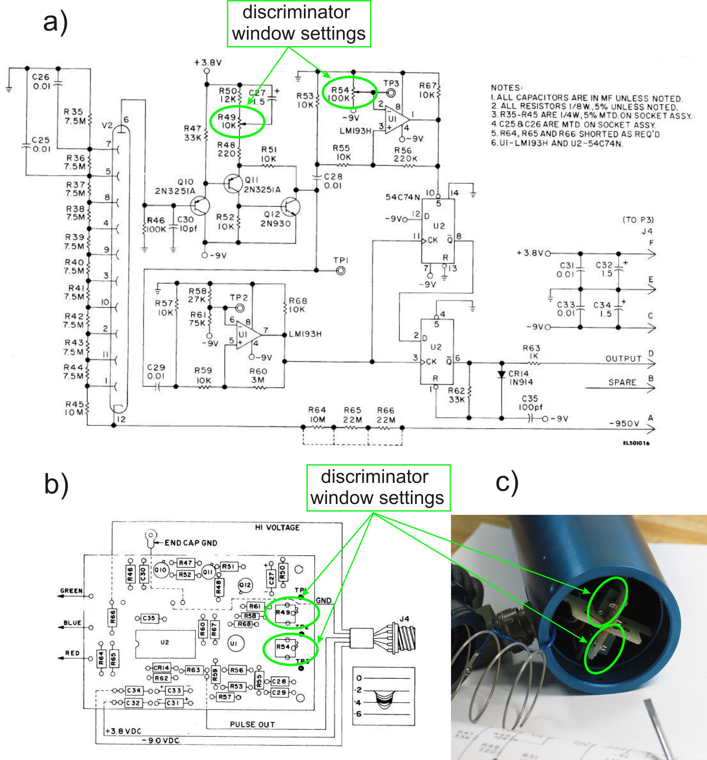
This PDF file presents the schematic diagram of a custom-built circuit designed to drive the PDR-56 probe. A JKL BXA-12579 inverter, typically used for powering cold-cathode fluorescent lamps, serves as the high-voltage power supply. The BXA-12579 generates 1,500 VAC...
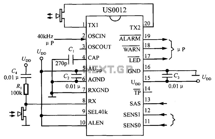
The circuit consists of the US0012 ultrasonic interference detection system, as illustrated in the accompanying figure. When the SEL40k termination is set to high, it selects a clock frequency of 40kHz. The US0012 module can perform several tasks: it...
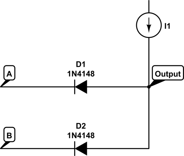
The voltage at the anode and cathode of the diodes is checked to determine whether they are conducting. There is confusion regarding the current source and how to determine the state of the diodes for input combinations (00, 01,...

Filter regulators, solenoid valves, quick exhaust valves, flowline pilots - Welcome to Bifold Fluidpower Ltd. Bifold Fluidpower Ltd. specializes in a range of fluid power components that include filter regulators, solenoid valves, quick exhaust valves, and flowline pilots. Each of...