
40 pin avr development board

The described prototype board serves as a versatile platform for developing applications using 40-pin Atmel ATMega microcontrollers. The board is equipped with several essential components to facilitate microcontroller operation and programming.
The power supply circuit is designed to provide stable voltage levels required for the microcontroller and peripheral devices. It typically includes voltage regulators that convert a higher input voltage down to the required levels, ensuring that the microcontroller operates within its specified voltage range.
An 8MHz crystal oscillator circuit is integrated into the design to provide a clock signal for the microcontroller. This oscillator is crucial for timing operations, allowing the microcontroller to execute instructions accurately. The circuit may include capacitors that help stabilize the oscillator's frequency.
The RS232 port allows for serial communication with other devices, enabling data exchange between the microcontroller and external equipment such as computers or other microcontrollers. This port adheres to standard RS232 voltage levels and pin configurations, ensuring compatibility with a wide range of devices.
A reset integrated circuit (IC) is included to manage the reset functionality of the microcontroller. This IC ensures that the microcontroller starts in a known state upon powering up or when a reset is triggered, which is critical for reliable operation.
A status LED provides visual feedback on the board's operational state. It can indicate power status, communication activity, or error conditions, depending on how it is configured in the circuit.
Finally, the 10-pin STK ICSP (In-Circuit Serial Programming) port is provided for programming the microcontroller directly on the board. This interface allows for easy updates and programming of the microcontroller without the need for removal from the prototype board, facilitating rapid development and testing cycles.
The use of FR-4 material, known for its good mechanical and electrical properties, ensures durability and reliability in various operating conditions. The board's thickness of 1.5 mm provides a sturdy platform for mounting components and handling during development. Overall, this prototype board is well-suited for experimentation and development with ATMega microcontrollers, combining essential features for a wide range of applications.Prototype board for 40 pin Atmel ATMega microcontrollers with power supply circuit, 8MHz crystal oscillator circuit, RS232 port, reset IC, status LED, and 10 pin STK ICSP port.FR-4, 1.5 .. 🔗 External reference
Related Circuits
A Lithium Polymer Ion Battery is included with the Lilypad Development Board from SparkFun. There is an inquiry regarding whether the battery will charge when it is connected to the Lilypad Arduino while simultaneously connecting the Lilypad Arduino using...
This board does not utilize the CTS256AL2 text-to-speech chip. However, both SpeechChips.com and JDR may still have some of these chips available for purchase. The board can accommodate the SPO chip and an amplifier, allowing it to connect to...
All resistors are 1/4W. The circuit is powered by 9...15V DC or AC. When In Circuit Programming (ISP) connectors are used, it is possible for the programmer to be powered from the target's power source. Diodes D2 and D6...
This adaptor lets me program 8 or 20 pin DIP devices using the In-System Programmer (ISP) described in Atmel's AVR910 application note. This circuit provides power and clocks for the part to be programmed and power to the ISP...
The pinout of the OBD-2 ISO 14230-4 (ISO-9141-2, KWP2000) RS-232 cable schematic and layout pertains to a 16-pin car OBD2 special connector. This connector is compatible with vehicles from most European and Asian manufacturers, including brands such as Alfa...
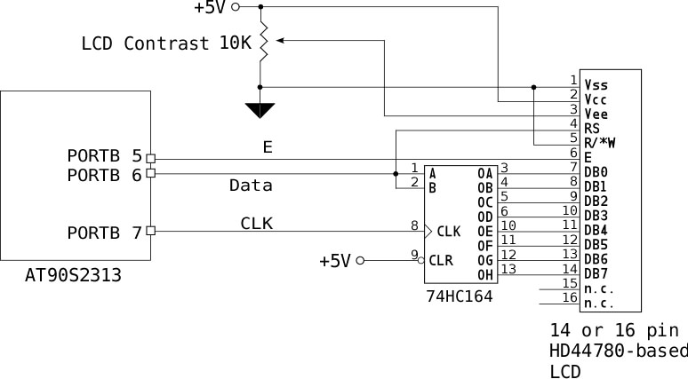
If no characters are displayed on the LCD and the hardware and software have been verified as functional, adjust the LCD Contrast potentiometer until the characters become visible. To send an 8-bit character or command to the LCD via...