
4017 CMOS Decade Counter

The described circuit appears to function as a sequential output generator that relies on clock cycles to control the state of multiple outputs. In this configuration, the clock signal serves as the primary timing reference, dictating the transitions of the outputs.
The circuit likely employs a flip-flop or a series of flip-flops to manage the state changes of each output. When the clock signal rises, the flip-flops are triggered to change their states. Specifically, the first output, designated as "0," is set to LOW, indicating an inactive state, while the second output, labeled "1," is set to HIGH, indicating an active state.
The design suggests a binary counting mechanism, where each subsequent clock cycle results in a shift of the output states. After the tenth output has been activated, the sequence resets, cycling back to the first output on the eleventh cycle. This behavior is characteristic of a ring counter or a shift register configured for a specific counting sequence.
To implement this circuit, a series of D flip-flops can be connected in a cascade configuration, with the output of one flip-flop serving as the input to the next. The clock signal would be connected to the clock input of all flip-flops to ensure synchronous operation. The outputs can be monitored through LEDs or other indicators to visually represent the state transitions. Additionally, resistors may be included in series with the outputs to limit current and protect the components.
Overall, this circuit effectively demonstrates the principles of digital logic and sequential circuits, showcasing how clock signals can be used to control multiple outputs in a predictable manner.On the rise of the second clock cycle, output "0" goes LOW and output "1" goes HIGH. This process continues across the tenoutputs and cycles to output "0" on the eleventh cycle. 🔗 External reference
Related Circuits
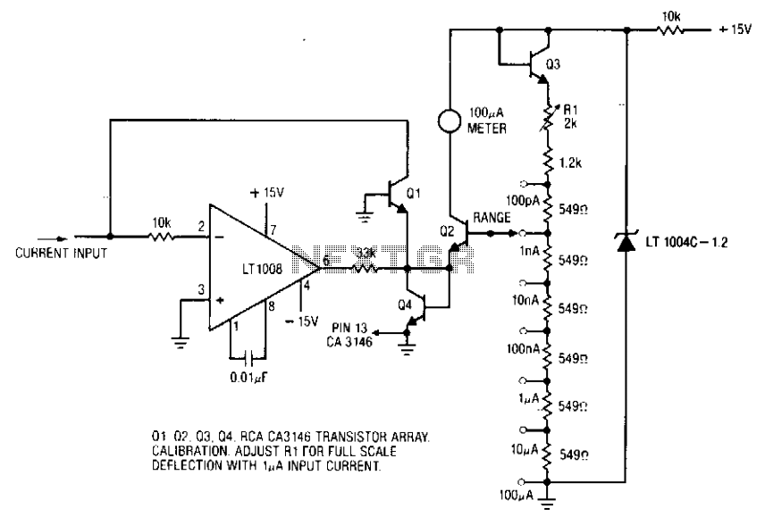
The ammeter measures currents ranging from 100 pA to 100 µA without the need for costly high-value resistors. Accuracy at 100 µA is constrained by the offset voltage between Q1 and Q2, while at 100 pA, it is limited...
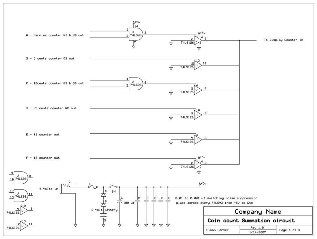
The outputs of all coin counters are summed in a 74LS126 tri-state buffer, which is used to connect all the counter outputs to the input. The circuit utilizes a 74LS126, a quad buffer/driver with three-state outputs, to manage the outputs...
This simple counter can be utilized to count pulses and serves as the foundation for a customer counter, similar to those found at store entrances, or for any application requiring counting functionality. The circuit is compatible with any TTL...
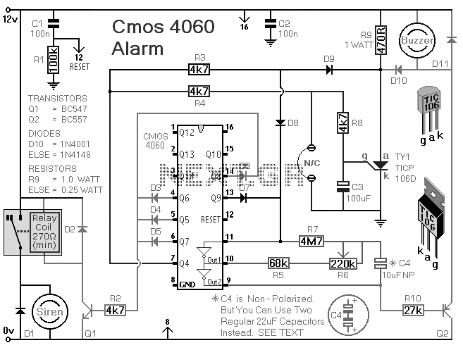
A CMOS 4060 burglar alarm circuit. This is a single-zone alarm with automatic exit, entry, and siren cut-off timers. It will accommodate all the usual types of normally-closed input devices, such as magnetic reed contacts. The CMOS 4060-based burglar alarm...

This simple counter can be used to count pulses, serving as the basis for a customer counter, similar to those found at the entrances of some stores, or for any other application requiring counting. The described simple counter circuit is...
The receiver is equipped with a larger motor to drive the wheels and a smaller motor for steering, which operates in a non-proportional manner. An additional channel can be incorporated into the receiver by utilizing the spare latch. The...