
7 segment led counter
The described simple counter circuit is a versatile device designed to tally pulses generated by various sources. It can effectively function as a customer counter, which is commonly utilized in retail environments to monitor foot traffic. The circuit can also be adapted for other applications where counting is necessary, such as in automated systems, event logging, or inventory management.
The core of the counter typically involves a digital counter IC, such as the 74HC4040 or a microcontroller, which can be programmed to increment its count with each pulse received at its input. The pulse input can be derived from a variety of sensors, including infrared sensors, mechanical switches, or phototransistors, depending on the specific application requirements.
The circuit design includes essential components such as resistors, capacitors, and possibly a display module (like a seven-segment display) to visually present the counted value. A power supply circuit is also necessary to ensure stable operation, which may involve a voltage regulator if the supply voltage needs to be adjusted.
For enhanced functionality, features such as reset buttons, debounce circuits for mechanical switches, and memory functions to retain counts during power loss can be integrated. The output of the counter can be configured to trigger alarms or notifications when certain thresholds are reached, further expanding its usability.
Overall, this simple counter circuit is a fundamental building block in electronic counting applications, providing a reliable and efficient means to track events or items in real-time.This simple counter can be used to count pulses, as the basis for a customer counter (like you see at the doors of some stores), or for anything else that may be counted.. 🔗 External reference
Related Circuits

The constant current function module is disabled at the port junction, which has 13 terminals. When the module is turned OFF, the constant current ban port also becomes inactive. The constant current function is lost when the module is...
This LED flasher circuit utilizes a 555 integrated circuit (IC) and is designed to drive multiple LEDs. Notably, connecting several LEDs in series does not increase the power consumption. The LED flasher circuit based on the 555 timer IC is...
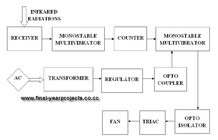
This report presents a comprehensive overview of a mini project titled "Remote Controlled Fan Regulator," developed in accordance with the curriculum requirements for the sixth semester of the Bachelor of Technology degree in Electrical and Electronics Engineering. The report...

This Outdoor LED Solar Garden Lights project is a hobby circuit for an automatic garden light that utilizes a light-dependent resistor (LDR) and a 6V/5W solar panel. During daytime, the internal rechargeable 6 Volt sealed lead-acid (SLA) battery is...
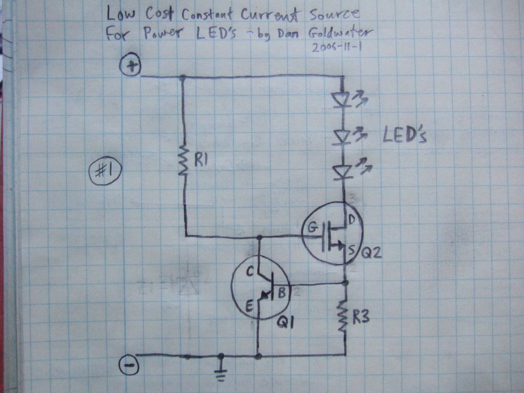
Here is a simple and inexpensive ($1) LED driver circuit. The circuit functions as a constant current source, ensuring that the LED maintains consistent brightness. The LED driver circuit is designed to provide a stable current to the LED, which...

This temperature-controlled relay circuit is a simple yet highly accurate thermal control circuit that can be used in applications requiring automatic temperature regulation. The temperature-controlled relay circuit operates by monitoring the ambient temperature and activating or deactivating a connected load...