
5 Minute Digital Clock

The clock circuit is designed to provide a simple yet effective timekeeping solution, leveraging common electronic components to achieve a reliable performance. The choice of the 32,768Hz tuning fork resonator is particularly important, as it serves as the basis for accurate timekeeping. This frequency is standard in digital clocks, allowing for precise division down to the required intervals. The use of counters such as the 7490 and 7492 facilitates easy manipulation of time intervals, ensuring that the clock can be set accurately to the nearest five minutes.
The implementation of the LM311 comparator as an oscillator offers flexibility in adjusting the time base, while the use of trimmer capacitors allows for fine-tuning, which is critical in achieving the desired accuracy. The design also includes provisions for user interaction through the minute and hour set buttons, enabling straightforward adjustments. The integration of the 74138 and 74139 decoders allows for a clear visual representation of time, with the LEDs providing a simple yet effective means of displaying the current hour and minute intervals. Overall, the circuit exemplifies a practical and educational approach to clock design, suitable for both hobbyists and those seeking to understand the fundamentals of digital timekeeping systems.The clock shows time in 5 minute intervals. The hour and minute can be set. There is no alarm or any AM/PM indicator. For the clock face I used a 2 pieces of lenolium glued together to increase thickness. (A couple of floor tiles would work as well. ) The numerals are just inexpensive adhesive characters I purchased at a hardware store meant for us e on mail boxes. The LEDs are glued to the clock face from behind. If you wanted to get fancy, a nice brass or wooden clock face can be made along with a wooden cabinet like a "grandfather" style clock. NOTE : In the following schematics, TTL devices are shown as 7400 series. These are used as generic 7400 series part numbers. During construction, 74LS, 74ALS or 74HCT should be used because of the low power requirements and availability.
(I know most of you know this already. ) The power supply is not shown in the schematics. A simple 5 volt regulated supply of 500mA to 1A will work well. I used a 7. 5V, 600 mA power transformer, a full wave rectifier and a 220 uf capacitor as a filter. Regulation is done with a LM340-5 - a 7805 would work just as well. For the full wave rectifier, I used a rectifier set in a TO-220 package that I salvaged from a switching power supply. The oscillator is a LM311 comparator along with a 32768Hz tuning fork type clock resonator. The 10pf trim cap is adjusted using a 6 digit frequency counter with the resolution of 1Hz. If you don`t have a 6 digit frequency counter, a fixed capacitor of 5 to 7 pf should get you close. I chose the LM311 circuit because the 311 is commonly available and inexpensive. There probably are better time base ICs available. The 32768Hz signal is divided by 16384 to get a 2Hz signal. This is done with a 74HCT4020 counter. The 2Hz signal is then divided by 12 with a 7492, then divided by 5 and 10 with 7490s. This gives a signal of one cycle per five minutes. The counters are reset when the minute is set. This is so that when the minute is set, the clock starts at the begining of a 5 minute cycle. For this reason it is important to set the clock upon true 5 minute intervals. The second schematic shows the 5 minute interval and 1 hour counting circuitry. The cluster of gates near the minute set button switches between the 5 minute signal and the 2Hz signal.
This way, the clock advances at a rate of 2Hz when the set button is held down. The 7493 is setup to reset at the 13th count (12). The C and D bits are sent to an AND gate which reset the counter at 12 and clock the next 7493 counter stage. The next counter stage being for hours. The second counter stage works just like the first one, reseting on the 13th count. The set circuitry uses the same gate circuit to switch between the 1 hour signal and the 2Hz signal which is used for setting the hour.
An inverter is connected to the D output of the counters and connected to the 74138 and 74139 decoders. This is done so that the 74138 decodes counts 0 through 7 while the 74139 is disabled. For counts of 8 through 11, the 74138 is disabled while the 74139 is enabled. This way, a full 1 of 12 decoding can be done to represent each hour and each 5 minute interval. This decoding circuit could have been done with a 74154. In fact, the 74154 could have also been used to reset the counters. I chose the `138 and `139 design because the `138 and `139 are commonly available while the `154 can be difficult to obtain these days.
The 74138 and 74139 decoders drive the LEDs directly. The outputs are active low (inverted) so the LEDs are tied to positive. The decoders are not designed to drive LEDs this way but they do. The resistor values for the LEDs will depend on the LED but I don`t advise going below 300 Ohms because this will stress the decoder chips. For high current LEDs, driver ICs or descrete transistor drivers may be used. Note about construction : I used wire wrap connection techniques with machine pin sockets, not wire wrap so
🔗 External reference
Related Circuits
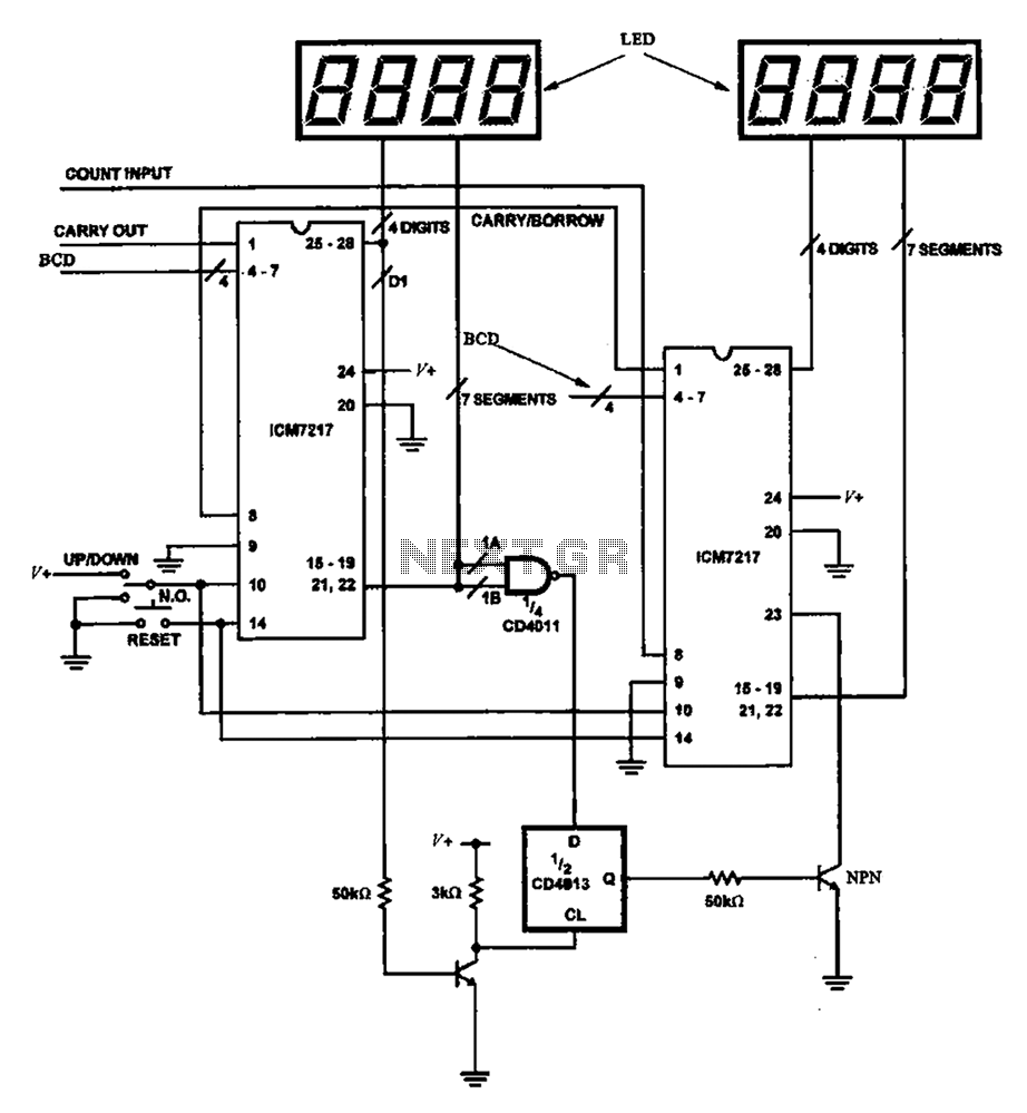
Figure 8 illustrates a potential digital counter circuit. This circuit employs two ICM7217 integrated circuits, with each controlling four digital display tubes. The digital counter circuit primarily utilizes the ICM7217, a highly integrated chip designed for driving seven-segment displays. Each...
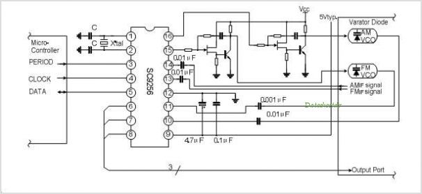
The SC9270C/SC9270D is a comprehensive DTMF receiver that integrates both bandsplit filtering and digital decoding functions. The filter section utilizes switched capacitor techniques to achieve high- and low-group filtering along with dial-tone rejection. The decoder employs digital counting techniques...
This circuit provides a visual 9-second delay using a 7-segment digital readout LED. When the switch is closed, the CD4010 up/down counter is preset to 9, and the 555 timer is disabled with the output held high. The circuit utilizes...
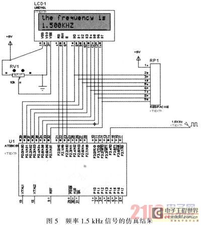
The primary function of the frequency counter is to measure the frequency and cycle of a signal. Its applications span a wide range, extending beyond simple instrument measurements to areas such as education, scientific research, high-precision instrument measurement, and...
Typical circuit representative of those used in most light switch type digital timers. The timer module is normally a PIC or custom chip, and it syncs to the AC line so that a trigger pulse can be supplied at...
An alternating display for a version 1 nixie clock inspired new logic designs for switching signals to the display. The design eliminated the 4013 flip-flop and two 4017 counters, leading to a redesign of the hours section and reset...