
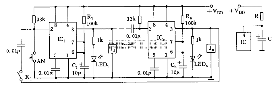
5-motor walker circuit

The P5 design effectively integrates a series of 74HC/AC240 chips to create a versatile control system for motor operations. The use of H-bridge configurations allows for efficient control of motor direction and speed, facilitating the movement of the robotic walker. The incorporation of photodiodes for light detection enhances the walker’s ability to navigate its environment, enabling it to respond dynamically to changes in light intensity. The design's master-slave configuration ensures synchronized operation of the motors, while the unique application of tri-state inverters for feedback and LED indication provides additional functionality. The power management system is designed for convenience and efficiency, ensuring that the walker remains operational without the need for frequent battery removal. Overall, the P5 design exemplifies a well-thought-out approach to robotic motor control, combining various electronic components to achieve a cohesive and functional system.The P5 design uses only eight 74HC/AC240 chips which are all octal inverting buffers. Each 74HC/AC240 chip has two groups of four inverters each controlled by a tri-state enable pin (pin 1 and 19). The 74AC240 chips (U1-U5) are used as H-bridge style motor drivers since they have almost double the drive current compared to 74HC240 chips.
These mot or driver chips are permanently enabled by grounding control pins 1 and 19. The two groups each have four inputs connected in common to a bicore output and the four outputs are connected in common to one motor winding terminal. Since each bicore has two complementary outputs the voltage across the motor winding causes the motor to rotate back and forth.
The 74HC240 chips U6 and U7 are each used to form a master - slave bicore pair with reverser. The inverters used for the bicore s are permanently enabled by grounding pin 1. The inverters used for reversing are turned on or off with the tri-state enable pin 19. Only 2 of the 4 tristate inverters are used conventionally for reversing the phase of the slave bicore s while the other two are put to a novel use: one inverter is used to provide positive feedback to the enable pin and the second spare inverter is used to turn on a RED flashing LED when the reverser is active. The flashing LED also provides diagnostic visual indication of the operation of the slave bicore. The 74HC240 chip used for U8 provides a reverser and a slave bicore for the waist motor as well as a monocore (a.
k. a High Low Oscillator) photobridge comparator which controls the phasing of the front and rear motors. I) The photobridge comparator uses 2 inverter s from U8 connected in series as an voltage controlled oscillator with complementary outputs to generate three states : If the left photodiode gets more light than the right photodiode, the two inverter complementary outputs are steady state DC.
The inverter with the low output reverses the left slave bicore and corresponding rear leg causing the walker to turn left. If the right photodiode gets more light than the left photodiode, the two inverter complementary outputs are steady state DC (opposite to a.
) The inverter with the low output "reverses" the right slave bicore causing the walker to turn right. If both photodiode s get equal light, the two inverter complementary outputs are pulsing and neither of the slave bicore s is reversed causing the walker to go straight.
II) Two master suspended bicore s in U5 and 6 are coupled at their inputs with a 7. 2M phase sync resistor so that they will oscillate in quadrature with their waveforms overlapping by 25%. These waveforms are connected to the 74AC240 motor driver which control the front legs. III) Two rear motor slave bicore s use inverter s from U5 an U6 with timing components that delay the slave bicore output by about 25%.
These are connected to the front leg motor drivers (6 inverters for each motor). IV) Two inverters in U6 and U7 are used for signal reversing and are connected between the outputs of each of the master bicore s (front legs) and the slave bicore s (rear legs) to control turning with enable signals from the photo comparator circuit. When the light is balanced pin 19 of U6 and U7 are both high, both reversers are turned off, the tristate inverter s are disabled and the walker moves straight.
VI) The waist reverser uses two inverter s in U8 and is connected between one output of each of the U6 and U7 master bicore s and the waist slave bicore circuit inputs described in V). The waist motor phase reversal occurs when one of two tactile switches is triggered by collision with an obstacle.
At that time the U8 tristate inverter s are enabled. VII) The power supply consists of a 6V NiCd battery and charger circuit with a three position switch for on-off and charging. A 78L05 is included for recharging a 900mAHr battery pack at 0. 1C without removing it from the walker. The photo compar 🔗 External reference
Related Circuits
The circuit depicted in the figure is designed for multi-temperature testing, allowing for the switching of the thermocouple corresponding to the active channel. At the core of this design is a 555 timer configured in a monostable delay mode....
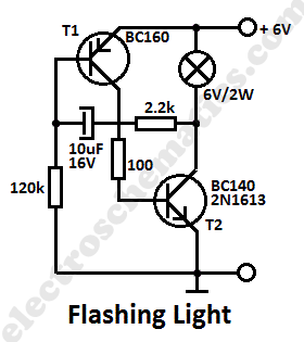
This simple flashing light circuit operates at 6 volts and 0.5A, exhibiting low current consumption when the light bulb is turned off. The frequency of the flashing is predetermined. The circuit consists of a power supply, typically a battery or...

A signal from an infrared (IR) remote control is converted from IR radiation to a frequency pulse that can be transmitted through coaxial TV cable or any other two-conductor wire to another room, where it is converted back into...
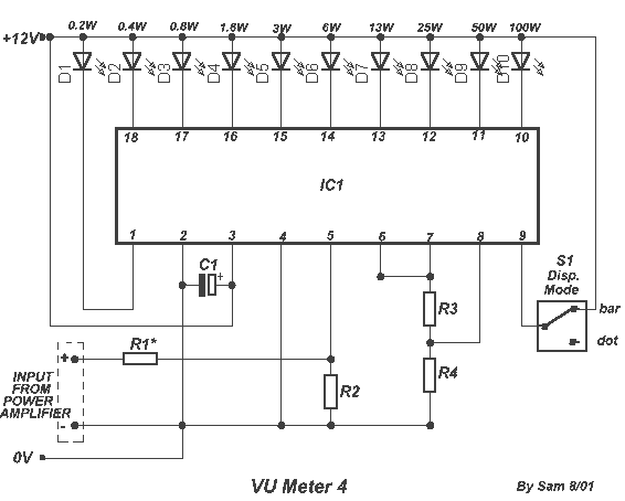
The circuit is placed parallel with the exit of power amplifier and gives the level of signal from output. Changing resistance R1 in the input circuit, we adapt the indication of power in the resistance of loudspeaker that we...

CB85-10 leakage protection circuit diagram, T for the trip coil, SB is the test button, Ri is simulated human resistance. The CB85-10 leakage protection circuit is designed to enhance safety by detecting leakage currents and disconnecting the electrical supply to...
Electrical signals travel along the neurons in the brain and body, continuously transmitting information throughout the complex system. Without these signals, the body would function like a plant, with different parts unaware of each other's conditions, making animal life...